connections with nuts on the inside.
Note: Tighten the nuts and bolts during assembly only to
the extent that they can not fall down.
If you tighten the nuts and bolts prior to final assembly, final
assembly can not be performed.
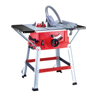
Mounting the bench extension (fig. 5)
1. Turn the saw and place it on the floor with the bench
facing down.
2. Align the bench extension (8) flush with the saw bench
(1).
3. Push table extension (8) onto the sawing table (1) using
the hex bolts (19) and cross member (21c). Repeat for the
opposite side.
4. Screw the support struts (21a, 21b) to the table
extensions (8) with the hex bolts (19) and cross member
(21c).
5. Subsequently, tighten all screws.
Mounting rack (figs. 6-7)
1. Screw the four support legs (16) together with the
support struts (21a, 21b) onto the saw with the hex bolts
(19) (fig. 6). For this use the saw blade key (21a), part of
the delivery contents (fig. 6).
2. Now place the rubber feet (16a) onto the support legs
(16) (fig. 6.1).
3. Now, screw the long centre brace (17) and the short
centre brace (18) onto the legs (16) using the hexagon
head bolts (19) and the hexagon head nuts (20). Make sure
that the same braces face each other. The long centre
braces (17 - marked „B“) must be mounted parallel to
the operator‘s side of the saw. (Fig. 7).
4. Using two hex bolts (19) on each, loosely secure hex
nuts (20) at the drill holes of the rear support legs of the
support frame (16b) (fig. 7.1).
Attention!
Both support frames must be fastened to the back of
the machine!
5. Then, tighten all the nuts and bolts of the underframe.
Setting / mounting the riving knife (figs. 8-10)
The setting Caution! Pull out the main plug!
The setting of the riving knife (6) must be checked prior
to commissioning. of the riving knife (6) must be
checked prior to commissioning.
1. Set the saw blade (3) to the max. cutting depth, bring it to
the 0° position and lock it.
Mounting / dismounting the saw blade guard (figs. 11-12)
1. Mount the saw blade guard (4) together with the bolt (25)
on top of the riving knife (6), so that the bolt is firmly seated in
the slot of the riving knife (6).
2. Do not screw in the bolt (25) too tightly; the saw blade
guard (6) must move freely.
3. Plug the suction hose (5) onto the suction adapter (26) and
the connecting piece of the saw blade guard (4). Connect a
suitable splint collector onto the suction adapter (26).
4. Disassembly is performed in reverse order.
Caution!
The saw blade guard (4) must be lowered onto the
workpiece before starting the sawing operation.
Replacing the bench insert (fig. 8)
1. In case of wear or damage, the bench insert (2) must be
replaced; otherwise, there is an increased risk of injury.
2. Unfasten the bolt (23) using a Phillips screwdriver.
3. Take out the worn bench insert (2).
4. The installation of the new bench insert is done in reverse
order.
Installing / replacing the saw blade (fig. 13)
1. Caution! Pull out the main plug and wear safety gloves.
2. Dismount the saw blade guard (4) (see 8.4)
3. Remove the bench insert (2) (see 8.5)
4. Loosen the nut by placing a saw blade spanner (22a) on
the nut while holding up another saw blade spanner (22b) on
the motor shaft (see fig. 22).
5. Caution! Turn the nut in the direction of rotation of the saw
blade.
6. Remove the outer flange and remove the old blade inner
flange.
7. Clean the saw blade flange thoroughly with a wire brush
before mounting the new saw blade.
8. Insert the new saw blade in reverse order and tighten.
Caution! Note the direction of run, the cutting slope of
the teeth must be in the direction of run, i.e. facing
forward.
9. Remount and adjust the bench insert (2) and saw blade
guard (4) (see 8.4 and 8.5)
10. Before you start working again with the saw, check proper
functioning of the safety equipment.
11. After fitting, check that the saw blade guard (4) is
functioning properly. Lift the saw blade guard and then
release it. The saw blade guard should automatically move
back to its starting position.
On/Off switch (Fig. 14)
• The saw can be switched on by pressing the green
pushbutton „I“. (11)
• The red pushbutton „0“ (11) has to be pressed to switch
off the saw.
Overload switch (10)
The device motor is protected against overload with an
overload switch (11a).
In the event of the nominal current being exceeded, the
overload switch (11a) switches the device off.
If this happens, proceed as follows:
• Let the device cool down for several minutes.
• Press the overload switch (11a).
• Switch the device on by pressing the green “I” button.
Cutting depth (Fig. 14)
Turn the round handle (12) to set the blade (3) to the
required cutting depth.
• Select the appropriate scale depending on whether the stop
rail (27) is rotated for processing thick or thin material:
High stop rail (thick material):
Low stop rail (thin material):
• Set the rip fence (15) to the desired level in the sight glass
and fix it with the eccentric lever for the rip fence (30).
• When mounting or adjusting the rip fence, ensure that the
rip fence is aligned parallel to the saw blade.
Transverse stop (fig. 18)
• Push the transverse stop (7) into a groove (31a/31b) of the
saw bench.
• Loosen the handle screw (32).
• Turn the cross stop (7) until the desired angle is set. The
arrow on the transverse stop is at the set angle.(0°-60°)
• Tighten the knurled screw (32) again.
• The stop bar (34) can be moved on the transverse stop (7).
Loosen the nuts (33) and push the stop rail (34) to the desired
position. Tighten the nuts (34) again.
Caution!
 Loading...