14 15
Assembly Assembly
Assembly for Wet Vacuuming – Foam Filter
WARNING: Never use the vacuum without a lter. Check that the lter
is securely tted at all times.
1. Remove the appliance head (2) from the tank (10) by unlocking the 2 x
side locking handles (6) pulling them outwards, then upwards (Fig A).
Place the appliance head (2) upside down onto a at surface, or on its side
(if the carry handle is already assembled).
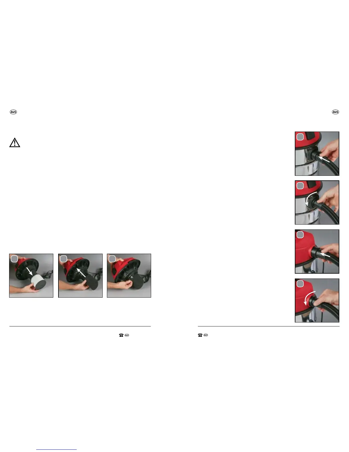
2. Remove the HEPA lter (16) (installed upon purchase) by pulling it away
from the appliance head (2) (Fig F).
3. Slip the foam lter (19) over the lter basket (14) (Fig.G). Ensure the foam
lter (19) covers the full lter basket (14) (Fig H).
NOTE: The foam lter (19) is only suitable for WET vacuuming.
IMPORTANT: Regularly clean the foam lter (19) and allow it to dry before
resuming vacuuming.
IMPORTANT: DO NOT use the HEPA lter for wet vacuuming (the HEPA
lter is pre-installed upon purchase).
IMPORTANT: The Wet and Dry Vacuum should only be connected
to a mains power supply socket; an RCD (Residual Current Device) is
recommended.
4. Re-assemble the appliance head (2) back onto the tank (10), and secure
the 2 x side locking handles (6).
NOTE: Always unplug the appliance after use and before cleaning or
changing the lters or accessories.
Fitting the Flexible Hose
Connect the exible hose (17) to the exible hose
outlet depending on the application required:
1. Vacuuming
Connect the exible hose (17) to the exible
hose outlet – suction (7) by inserting into the
outlet and aligning the arrow and locking pin
on the end of the exible hose (17), with the
arrow and ridge on the top of the exible hose
outlet – suction (7). This should ensure the
locking pin on the exible hose (17) aligns
with the ridge in the exible hose outlet –
suction (7). Rotate the exible hose (17) to the
left to secure the hose into position (Fig I/J)
2. Blowing
Connect the exible hose (17) to the exible
hose outlet – blowing (8) by inserting into the
outlet and aligning the arrow and locking pin
on the end of the exible hose (17), with the
ridge on the top of the exible hose outlet –
blowing (8). This should ensure the locking pin
on the exible hose (17) aligns with the ridge
in the exible hose outlet – blowing (8). Rotate
the exible hose (17) to the left to secure the
hose into position (Fig K/L)
H.
I.
J.
K.
L.
G.F.
 Loading...