Wulftec / M.J. Maillis Group
Page 22 of 36
Version 1.7.1 /November 2014
4
1
0
1
0
4 3 2
1
Operate
DarkLight
S
e
n
s
i
t
i
v
i
t
y
P
o
w
e
r
S
i
g
n
a
l
O
u
t
p
u
t
S
14
10
5
1
0
0 00 0
0 0
1
0
0 0
X1
1
0
X X
X1X X
1234
Time delay
Off DelayOn Delay
1
23
Setting Wrap Parameters (Cont’d)
Photoeyes Settings (Cont’d)
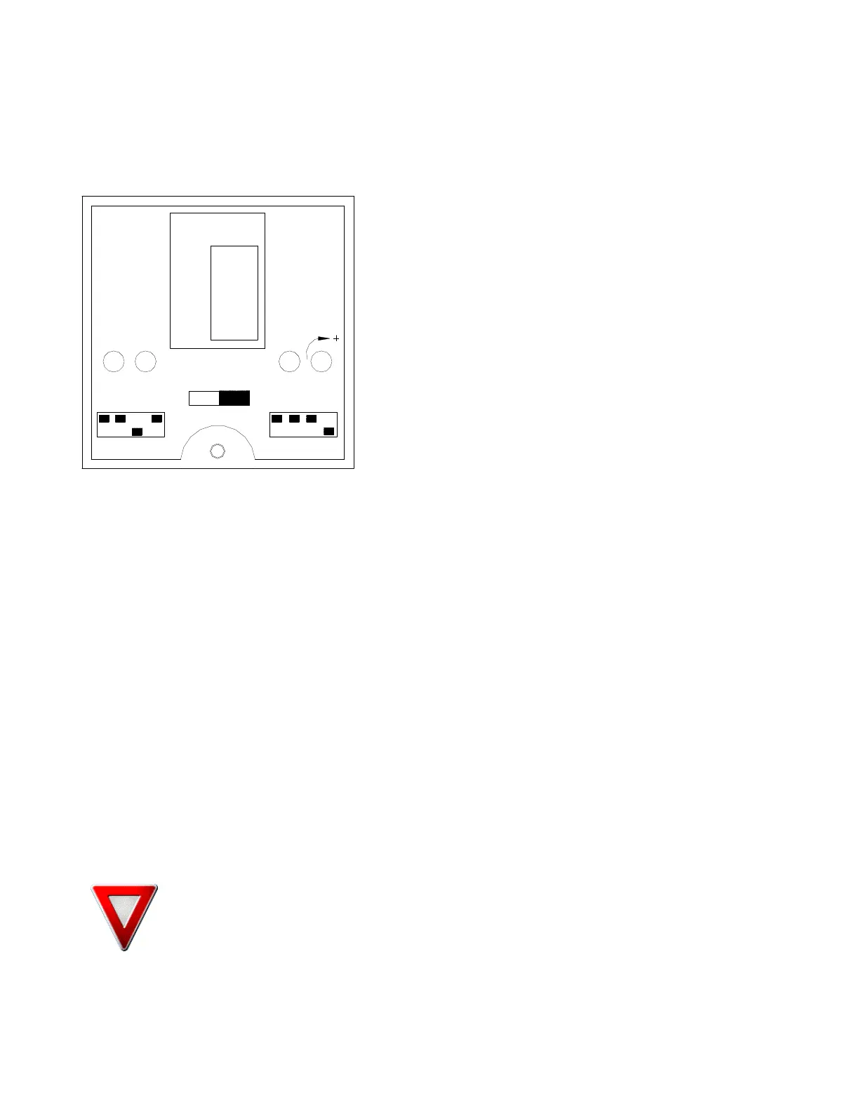
Figure 6 Diffuse Photoeye (special applications)
LED Indicators
Each sensor features three LED indicators to help you
program and use the sensor.
Green
The green LED indicates “power”. When this indicator is
lit, power is on.
Amber (Yellow)
The amber or yellow LED indicates “output.” This
indicator will light when there is an output. In AC
versions, this indicator shows that the relay is closed. In
DC versions, this indicator shows that the transistor is
switched according to the light/dark switching that has
been set.
Red
The red LED indicates “signal strength.” This indicator is solid when the signal is good; it flashes
when the signal is marginal. This indicator is especially helpful for use in alignment or to determine
whether dirt and dust build-up will interfere in operation. A flashing signal strength indicator will
trigger the alarm output.
Light/Dark Switching
Light and dark switching can be toggled using the switch below and between the red signal strength
and green power LEDs. Simply move the switch toward “light” for light switching or “dark” for dark
switching.
Sensitivity Adjustment
Using a small screwdriver, turn the sensitivity adjustment, located to the right of the green power
LED. To increase sensitivity, turn clockwise; to decrease sensitivity, turn counter-clockwise.
Time Delay
The on and off delays may be set simply by using the small dip switches on the top of the housing.
On these versions, a grid titled “Time Delay” appears in the center of the top panel, above and
between the red signal strength LED and the green power LED. The grid provides a key to the
positions of the dip switches for various time delays. Find the delay you want (between 0 and 14
seconds) on the grid and, using the 4 numbers to its right, toggle the dip switches between 0 and 1
as needed.
WARNING! The photoeyes are factory set for average loads at maximum rotation speed
and maximum carriage speed. Your particular wrap parameters may require alternate
settings for proper height sensing.
 Loading...
