23
©2002 Xantrex Technology Inc. All Rights Reserved.
P/N 975-0049-01-01 Rev A 10/2002
3.0 Operation
Basic Control Panel Features
The Trace UR-UPS control panel includes the following
items.
• A slide switch for setting its mode of operation: INVERT,
CHG, or SEARCH
• Green STATUS LED - indicates whether or not the unit is
active
• Yellow CHARGER status LED - indicates that the unit is
in charger mode
• Red/Yellow ERROR status LED - indicates an error
condition
See Table 3-1 for a description of the various
meanings of the LED indicators.
• Battery Voltage Meter - indicates the voltage level of the
batteries
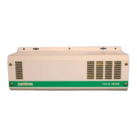
Figure 3-1
Trace UR-UPS Control Panel
Operational
Status LED
Charge
Status
LED
Error
Status
LED
Slide Switch
Battery
Voltage
Meter
 Loading...