25
3.0 Operation
©2002 Xantrex Technology Inc. All Rights Reserved.
P/N 975-0049-01-01 Rev A 10/2002
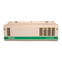
LED Indicators
The side panel contains LEDs indicating the unit’s
status. These LEDs flash at predetermined rates to
indicate a specific mode of operation or error condition.
Table 3-1
Status Indicator LEDs
SROTACIDNIDEL
DEL
noitacidnInoitpircseD
SUTATS
)neerG(
FFO
.ffositinuehT
gnihsalF
.edomHCRAESnisitinuehT
diloS
.edomTREVNInisitinuehT
REGRAHC
)wolleY(
hsalFwolS )dnocesrepecno(
teytonsahretrevni,tneserpsiCAytilitU
yllausussecorpsihT.edomegrahCotderrefsnart
sirewopytilituretfasdnoces02tuobasekat
.retrevniehtotdeilppa
hsalFtsaF )dnocesrepnet(
ehtniseirettabehtgnigrahcsiregrahcehT
.edomnoitprosba/klub
wolleYdiloS
.edomtaolfehtnignigrahcsiregrahcehT
rorrE
)wolleY/deR(
wolleY diloS
NOITIDNOCYRETTAB-HGIHegatlovyrettabehT.
.stimilstinuehtsdeecxe
wolleY gnihsalF
NOITIDNOCYRETTAB-WOLsiegatlovyrettabehT.
.stimilstinuehtwoleb
deRhsalFwolS )dnocesrepecno(
foerutarepmetehT.PMETREVOREMROFSNART
.slevelefassdeecxeremrofsnarteht
deRhsalFtsaF )dnocesrepnet(
nosTEFehtfoerutarepmetehT.PMETREVOTEF
.slevelefassdeecxedraobtiucriceht
deRdiloS
.NOITIDNOCDAOLREVO
Battery Voltage Meter
The Battery Voltage Meter provides a visual indication of
the battery voltage level. If the voltage is below 10 Vdc
(20 Vdc for 24-volt units), then the left most LED will
blink. If the voltage is above 15 Vdc (30 Vdc for 24-volt
units), then the right most LED will blink. Between these
voltages, the display changes at ½-volt increments
(1-volt increments for 24-volt units).
 Loading...