16
24V
GND
FM
0 50kHz/0 10V~~
020mA/010V~~
TA
TB
TC
U
V
W
E
M
GND
AI2
AI1
+10V
CM
X5
X6
X4
X3
X2
X1
R
S
T
I
I
OO
O
V
V
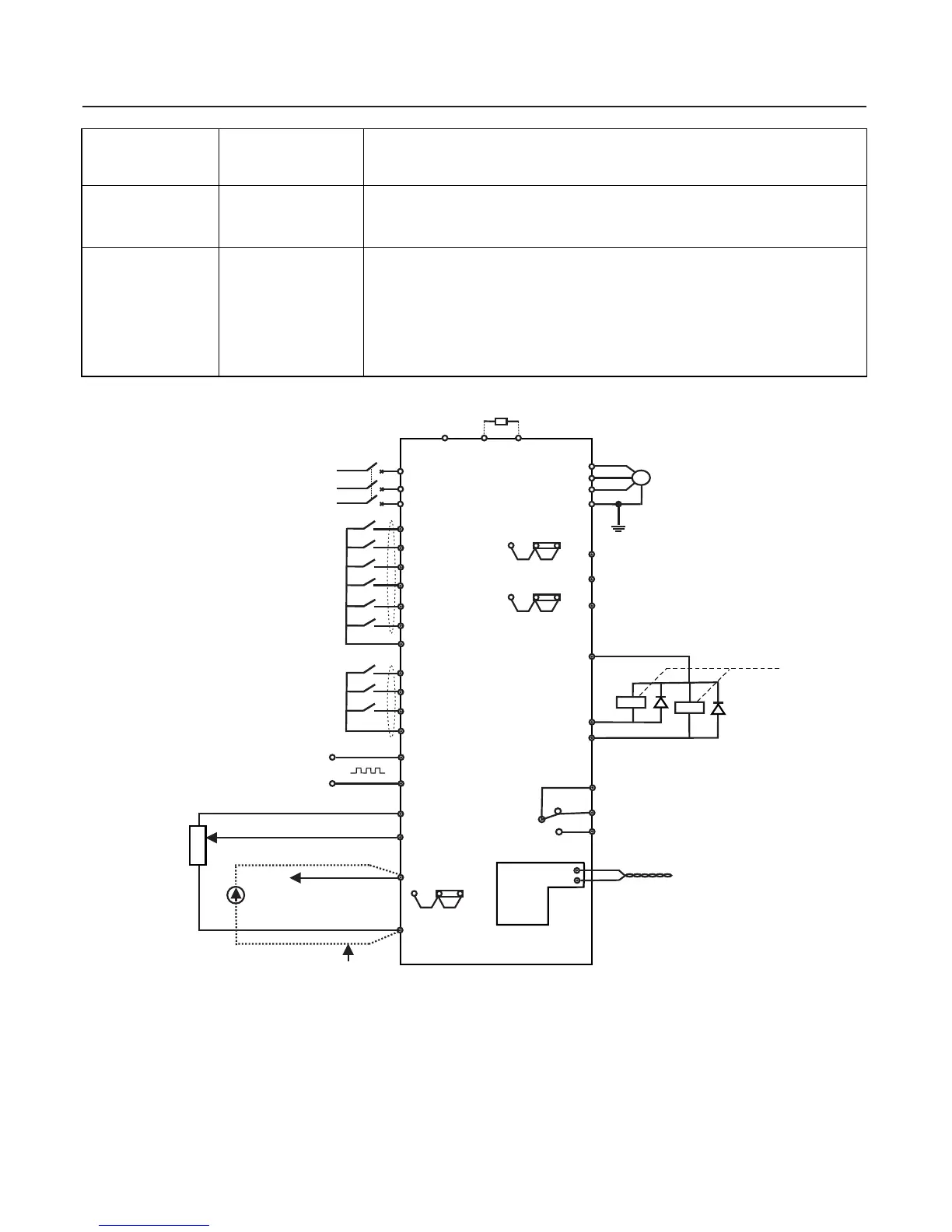
Frequency source 0 10V:~
Frequency source 0 10V:~
When selecting the 0 20mA reference~
Note : This figure is suitable for EH640A 7.5G (11P) and lower equipment , inverter with other power levels
refer to the main circuit and wiring schematic diagram in next section.
Fig . 3-3 Basic Wiring Schematic Diagram
A
O
2
V
2
A
A
O
I2
1
1
O
C
2
PB
Brake resistor
Circuit breaker
3-phase input
Positive rotation instruction
Reverse rotation instruction
Fault reset
Pulse input
Multi-function digital terminal
Electromotor
Ground
Relay
Open collector output
Programmable relay output
Standard RS485 interface
MODBUS digiboard
(optional)
Auxiliary DC source
PP
O
C
1
+-
CM
GND
FWD
REV
RST
DI
A
B
Chapter 3 Mechanical and Electrical Installation
AC input reactor Inverter input
Inverter DC Bus side
Connected between the
inverter output and
motor , its location
should be as close to the
inverter as possible .
1) Improve the input power factor ;
1) Improve the input power factor ;
1) Degrade the motor insulation performance and damage the motor for the long run .
2) Generate large leakage current and cause frequent inverter protection .
In general , the distance between the inverter and motor exceeds 50m . Installation of
output AC reactor is recommended .
2) Improve the whole efficiency and thermal stability of the inverter ;
3) Eliminate the impact of higher harmonics of the input side in the inverter and reduce
the external conduction and radiation interference .
The inverter output side generally has higher harmonics.when the motor is far from the
inverter , since there are many distributed capacitors in the circuit , certain harmonics
may cause resonance in the circuit and bring about the following two impacts :
3) Eliminate the input current unbalance due to the unbalance between the power phases .
2) Eliminate the higher harmonics of the input effectively and prevent other equipment
from damaging due to distortion of voltage wave ;
AC output reactor
DC reactor
3、Wiring Mode
 Loading...