52
~
F4. 04( F4. 06)
F4. 05( F4. 07)
break protract
Select control
signal
OC terminal
output status
close protract
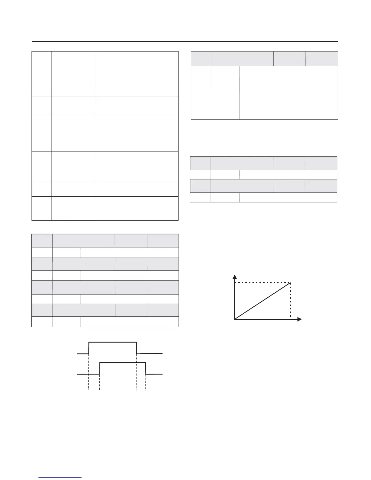
Schematic Diagram for
OC Output Closed/Break Protract
Fig.6-11
2 When AO2 output 0 to 50KHz pulse signal
, it can change the maximum frequency through
adjusting AO2 gain coefficient , the actual output maximum
frequency Y F4.10/100% * 10kHz
:
=
selects to
:
(0 50kHz)
0V
5V
0.0Hz
upper limit frequency
Setup : the first part of F4.08 is 0 F4.09=50.0% F4.11=0、、
Prompt : Please make sure AO1 jumping wiring hat of CUP is
placed on the right side .
Application examples of AO output analog signal are shown as
the following
Client hopes that AO1 outputs content selection
running frequency (0.0Hz to the upper limit frequency)
corresponding AO1 output 0 to 5V voltage signal
These are shown as the following figure .
:
:
:
Client hopes that AO2 outputs content selection
inverter output current (0 to twice rated current)
corresponding AO2 output 0 to 20KHz pulse signal
These are shown as the following figure .
:
:
00
Output channel
selection
O
A
F4.08
Chapter 6 Parameter Description
19
When terminal X1 enabled , the
output terminal enabled at once
, then after the F4.05,
F4.07 and FD.03 , the output
terminal disabled .
setup time of
Limitative time
output terminal
X1
25
Reference length
arrival
When the measured actual
length exceeds the setup value
of FA.06, it outputs ON signal .
The inverter allows to run and
output the trigger signal when it
is not at running status .
When PID running is in dormant status .
It outputs when accords with
the disconnection judgement terms .
When the inverter in running
status , it outputs ON signal .
It starts output when output
frequency lower than FDT2 at
the first time , the time length is
setting by OC break protract .
Three-line
running mode 1
start to trigger
information
output by itself
Band-type brake
information
output
Disconnection
detection output
Ready for
running
Dormant
21
22
23
24
20
Setup range
Factory
default value
0 1000.0S~
0 1000.0S~
0 1000.0S~
0 1000.0S~
0.0s
0.0s
0.0s
0.0s
F4.04
F4.05
F4.06
F4.07
Setup range
Setup range
Setup range
Setup range
Factory
default value
Factory
default value
Factory
default value
Factory
default value
OC1 close protract
OC1 break protract
OC2 close protract
OC2 break protract
Prompt AO1 and AO2 output different physics quantity by
setting jumping wiring ,the factory default output is voltage
signal , if want to output current or pulse signal , please placed
the jumping wiring hat ot the CPU on the left .
100.0%
AO1 output gain
F4.09
1.0% 500.0%~
100.0%
AO2 output gain
F4.10
1.0% 500.0%~
1 When AO1 outputs voltage and current signals , and AO2
outputs voltage signal selection , the output gain coefficient is
generally used to correct the analog output deviation .
:
The first part of LED AO1 output
selection
0 0 10V or 0 20mA
1 2 10V or 4 20mA
The second part of LED
0 0 10V 1 2 10V
205
:
:~ ~
:~ ~
:
:~ :~
:
AO2 output
selection
~ 0KHz high-speed pulse output
Factory
default value
Factory
default value
Setup range
Setup range
Prompt: When AO1andAO2 output different physics quantity,
jumping wiring setting is needed. The factory default output
is voltage signal, if you want to output current or pulse signal,
please placed the jumping wiring hat of the CPU on the left.
 Loading...