1 8191~
1 8191~
FV.10 : AI1
FV.11 : AI2
2
2
2
2
2
2
2
2
2
2
2
2
2
2
2
2
2
2
2
2
2
2
2
2
2
2
=
=
=
=
=
=
=
=
=
=
=
=
=
=
=
=
=
=
=
=
=
=
=
=
=
=
1
1
0
0
1
1
2
2
3
3
4
4
5
5
6
6
7
7
8
8
9
9
10
10
11
11
12
12
2
2
4
4
8
8
16
16
32
32
64
64
128
128
512
512
1024
1024
2048
2048
4096
4096
256
256
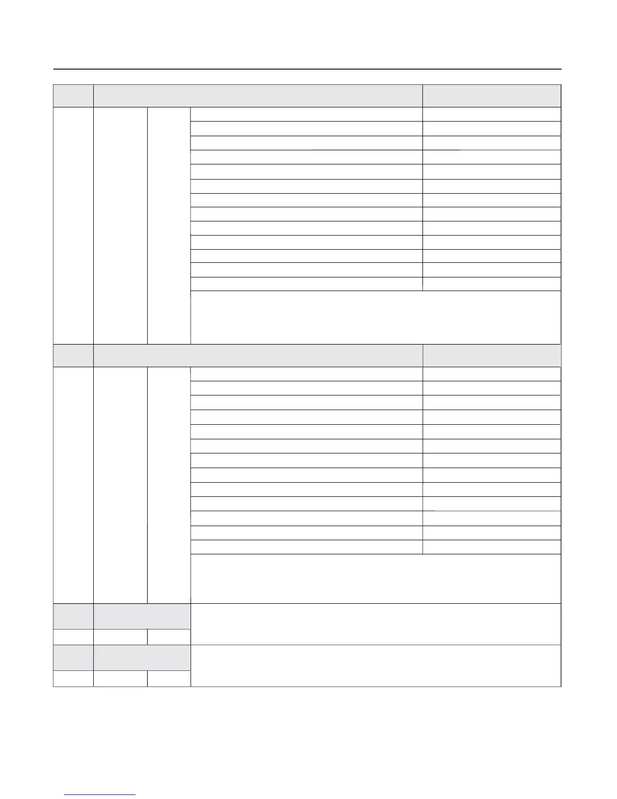
If the above parameters need to be displayed during the operation , set the corresponding bit
as 1 , and set them into F6.01after changing the binary numbers into decimal numbers.
If the above parameters need to be displayed during the operation , set the corresponding bit
as 1 , and set them into F6.02 after changing the binary numbers into decimal numbers.
Attached fig.3
The corresponding relationship between binary in F6.03 and FV parameter number is
as same as that of F6.01
0 8191~
1 8191~
56
F6.01
F6.02
F6.03
F6.04
LED running display parameter 1
LED running display parameter 2
LED stop display
parameter 1
LED stop display
parameter 2
Setup range
Setup range
Setup range
Setup range
Corresponding relationship
between binary and decimal
Corresponding relationship
between binary and decimal
FV.00 : Output frequency
FV.01 : Setup frequency (flashes)
FV.02 : Output current
FV.03 : Running rev
FV.04 : Setup rev (flashes)
FV.05 : Running load speed
FV.06 : Setup load speed (flashes)
FV.07 : Output voltage
FV.08 : Bus voltage
FV.09 : Input AC voltage
(DI)
FV.12 : Pulse reference
(Flashes)
FV.13 : PID setup
FV.14 : PID feedback
FV.15 : Terminal status
FV.16 : Actual counting value
FV.17 : Setup counting value (flashes)
FV.18 : Actual length
FV.19 : Setup length (flashes)
FV.20 : Actual running time
FV.21 : Setup running time (flashes)
FV.22 : AO1 output
FV.23 : AO2 output
FV.24 : Radiator temperature
FV.25 :Total running time
Chapter 6 Parameter Description
The corresponding relationship between binary in F6.04 and FV parameter number is
as same as that of F6.02
 Loading...