58
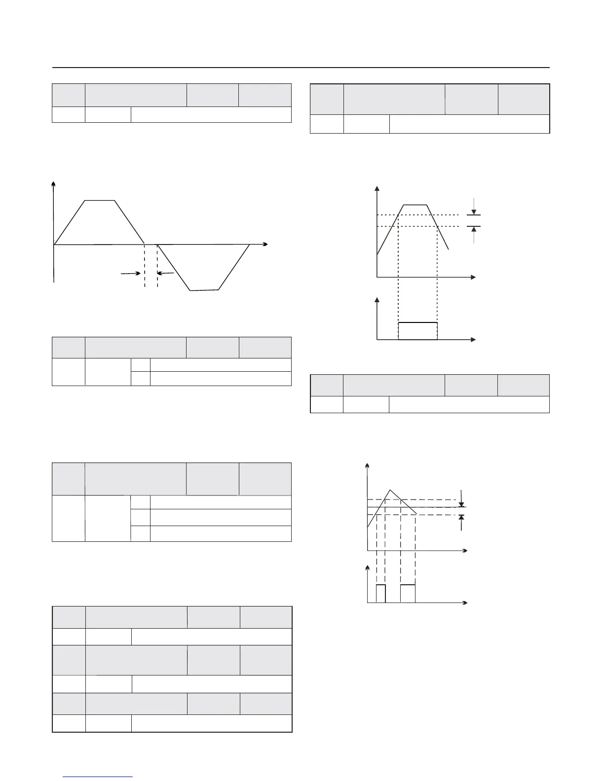
During the setting of forward/reverse rotation of the inverter ,
the transition time at the output zero frequency position.
It is shown as the following figure :
Fig.6-15 Schematic Diagram of Forward/Reverse Rotation
Dead-zone Time
0 Actived
1
Disabled
when the parameter is set as 0 Reverse rotation running
actived
:
when the parameter is set as 1 Reverse rotation running
disabled
:
The parameter is enabled for all command sources .
0
Run with frequency lower limit
1
stop
0.0Hz the maximum frequency F0.11~
0.0Hz the maximum frequency F0.11~
0.0Hz the maximum frequency F0.11~
0.0Hz the maximum frequency F0.11~
It is used to set the detection value of output frequency and
output the hysteresis value removed by the action .
It is used to select the running status of the inverter when the
setup frequency is lower than the frequency lower limit .
In order to avoid the motor always running with low velocity,
can be used to stop .this function
When the output frequency of the inverter reaches the setup
frequency value , this function can be used to adjust the
detection amplitude , it is shown the following figure .as
Fig.6-17 Schematic Diagram for Detection Amplitude
Setup
frequency
Output frequency
Detected Amplitude
Time
Time
Output frequency
Running time
dead zone time
ON
1
0
F7.13
F7.14
F7.19
2.00Hz
F7.15
F7.16
F7.17
F7.18
50.00Hz
2.00Hz
50.00Hz
2.00Hz
2
Running with zero velocity
0.0 3000.0s~
0.0s
F7.12
Factory
default value
Factory
default value
Factory
default value
Factory
default value
Factory
default value
Factory
default value
Factory
default value
Factory
default value
Setup range
Setup range
Setup range
Setup range
Setup range
Setup range
Setup range
Setup range
Forward/reverse
rotation dead-zone time
Chapter 6 Parameter Description
Reverse control
Setup frequency lower
than frequency lower
limit action
Frequency detection
value ( FDT1 level )
Frequency detection
hysteresis
( FDT1 hysteresis )
Frequency detection
value ( FDT2 level )
Frequency detection
hysteresis
( FDT2 hysteresis )
Output Terminal
Fig.6-16 Schematic Diagram for FDT Level
ON
Output frequency
FDT1 Hysteresis
Output Terminal
FDT1 Level
Time
Time
Frequency arrival
detection amplitude
0.0Hz the maximum frequency F0.11~
 Loading...