State Machine 117
Xilinx Blocks
A block diagram of this type of state machine is shown below:
Figure 3-80: Moore State Machine block diagram
The block is configured by providing a next state matrix and an output array. They
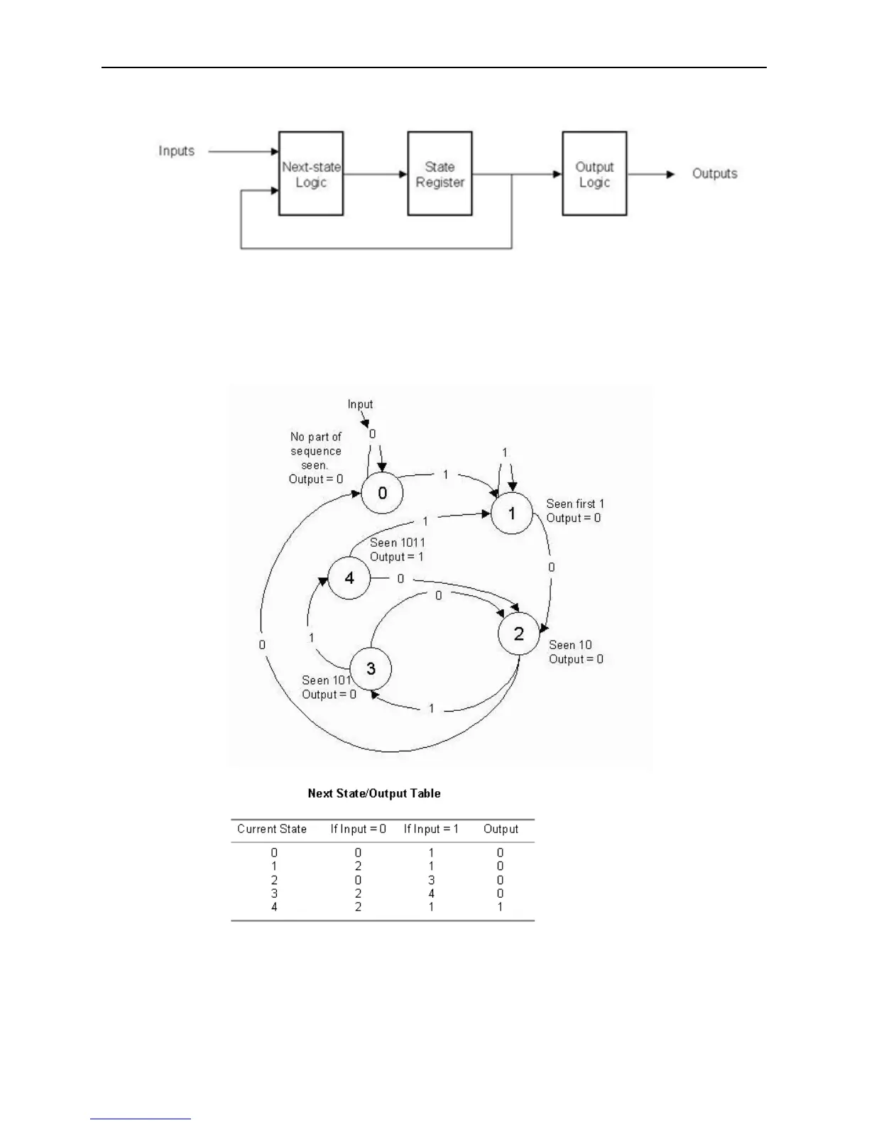
are defined by the state machine’s next state/output table. For example, consider the
problem of designing a state machine to recognize the pattern ’1011’ within a serial
stream of bits. The state transition diagram and equivalent transition table are shown
below.
Figure 3-81: Moore State Machine example transition diagram and table
The table lists the next state and output that result from the current state and input.
For example, if the current state is 4, the output is 1, indicating the detection of the
desired sequence, and if the input is 1, the next state is state 1.