XC4000 Series Field Programmable Gate Arrays
4-36 September 18, 1996 (Version 1.04)
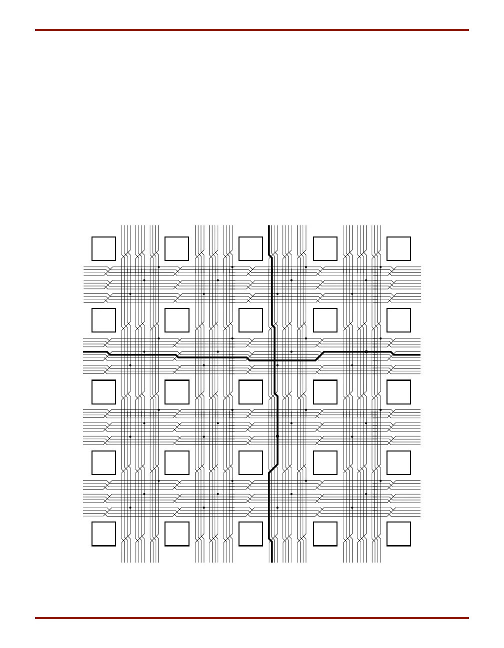
Quad Lines (XC4000EX only)
XC4000EX devices also include twelve vertical and twelve
horizontal quad lines per CLB row and column. Quad lines
are four times as long as the single-length lines. They are
interconnected via buffered switch matrices (shown as dia-
monds in Figure 27 on page 34). Quad lines run past four
CLBs before entering a buffered switch matrix. They are
grouped in fours, with the buffered switch matrices stag-
gered, so that each line goes through a buffered switch
matrix at every fourth CLB location in that row or column.
(See Figure 30.)
The buffered switch matrixes have four pins, one on each
edge. All of the pins are bidirectional. Any pin can drive
any or all of the other pins.
Each buffered switch matrix contains one buffer and six
pass transistors. It resembles the programmable switch
matrix shown in Figure 28, with the addition of a program-
mable buffer. There can be up to two independent inputs
and up to two independent outputs. Only one of the inde-
pendent inputs can be buffered.
The place and route software automatically uses the timing
requirements of the design to determine whether or not a
quad line signal should be buffered. A heavily loaded sig-
nal is typically buffered, while a lightly loaded one is not.
One scenario is to alternate buffers and pass transistors.
This allows both vertical and horizontal quad lines to be
buffered at alternating buffered switch matrices.
Due to the buffered switch matrices, quad lines are very
fast. They provide the fastest available method of routing
heavily loaded signals for long distances across the device.
CLB
CLB
CLB
CLB
CLB
CLB
CLB
CLB
CLB
CLB
CLB
CLB
CLB
CLB
CLB
CLB
CLB
CLB
CLB
CLB
CLB
CLB
CLB
CLB
CLB
X6602
Figure 30: Quad Lines (XC4000EX only)
 Loading...