4
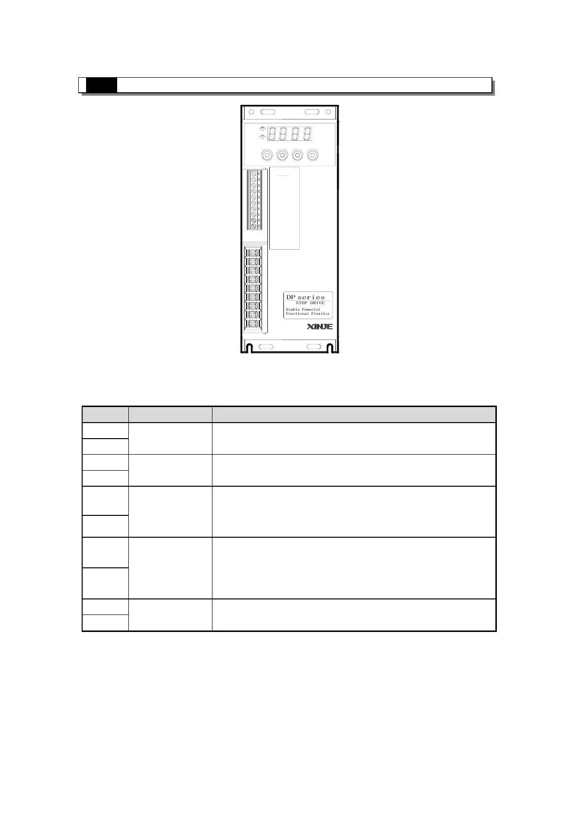
3. Interface and function
POWER
CHARGE
STA/ESC INC DEC ENTER
U
V
W
PE
L
N
PE
P+
PB
CAUTION!
·Make sure the
connection is
·Don't touch
the terminals
when running.
correct before
power on.
3-1. Control signal interface
3-1-1. Function
RS485 communication ; A: RS485+, B:RS485-
The motor moves one step at the rising edge of the signal. PUL-
high voltage 4~5V, low voltage 0~0.5V.
High/low voltage effective. Change the direction of the motor, the
original direction of the motor is decided by the wiring,
exchanging any phase can change the motor direction.
To release the motor. When ENA+ connects to 5V and ENA-
connects to low voltage, the driver will cut all phase current and
be in free state, stepper pulse will not be responded. Please let the
terminals vacant if out of use.
Output over-voltage, over-current signal.
3-1-2. Sequence chart of control signals
In order to ensure the system response reliability, the control signals should meet the
following requirements:
The signal effective high voltage is 24V; effective low voltage is less than 0.5V.
ENA (enable signal) should change to low voltage 3μs before DIR (direction
signal).
 Loading...