V5 series inverter
70
7 Upper limit of output frequency (FH) 18
DC brake when stop
8 Lower limit of output frequency (FL) 19
High and lower limit of swing frequency
9 Inverter zero speed running 20 Reach the preset running time
10 Simple PLC running completed 21
Instructions of the functions shown in Tabel 4-6:
0: Inverter is running(RUN). Inverter is running and the terminal outputs indication signal.
1: Frequency arriving signal (FAR). Refer to P4.12.
2: Frequency level detection(FDT1). Refer to P4.11~ P4.12.
3: Frequency level detection(FDT2). Refer to P4.13~P4.14.
4: Overload pre-alarm(OL). If the output current is higher than the value in P4.24 and the time is longer than the value in
P4.25, the inverter will output indicate signals. This function is mainly used in pre-alarm.
5: Inverter under voltage lock and stop(LU). While inverter is running, if the bus voltage is lower than setting level,
LED will show E-11.
6: External fault stop(EXT). Inverter outputs indication signal when it show E-13 alarm (error trip) .
7: Output frequency arrive upper limit(FH). An indicate signal will be output if setting frequency≥upper limit of
frequency and the running frequency arrives the upper limit of frequency.
8: Output frequency arrive lower limit(FL). An indicate signal will be output if setting frequency≤lower limit of
frequency and the running frequency is lower than low limit of frequency.
9: Inverter zero speed running. An indicate signal will be output when inverter output frequency is 0 and is still in run-
ning status.
10: Simple PLC running completed. An indicate signal (single pulse signal, 500ms width) will be output if the simple
PLC running is completed.
11: PLC one period running is completed. An indicate signal (single pulse signal, 500ms width) will be output if one
cycle running of simple PLC is finished.
12: Reach the setting counter value
13: Reach the setting middle counter value
12, 13 refer to P4.22~P4.23 for details.
14: Inverter running preparation is completed(RDY). This signal outputting means inverter bus voltage is normal,
running prohibition terminal is invalid, enable to accept startup command.
15: Inverter fault. If there is fault when inverter is running, indicate signal will be output.
16: Running at start frequency
17: DC brake when startup
18: DC brake when stop
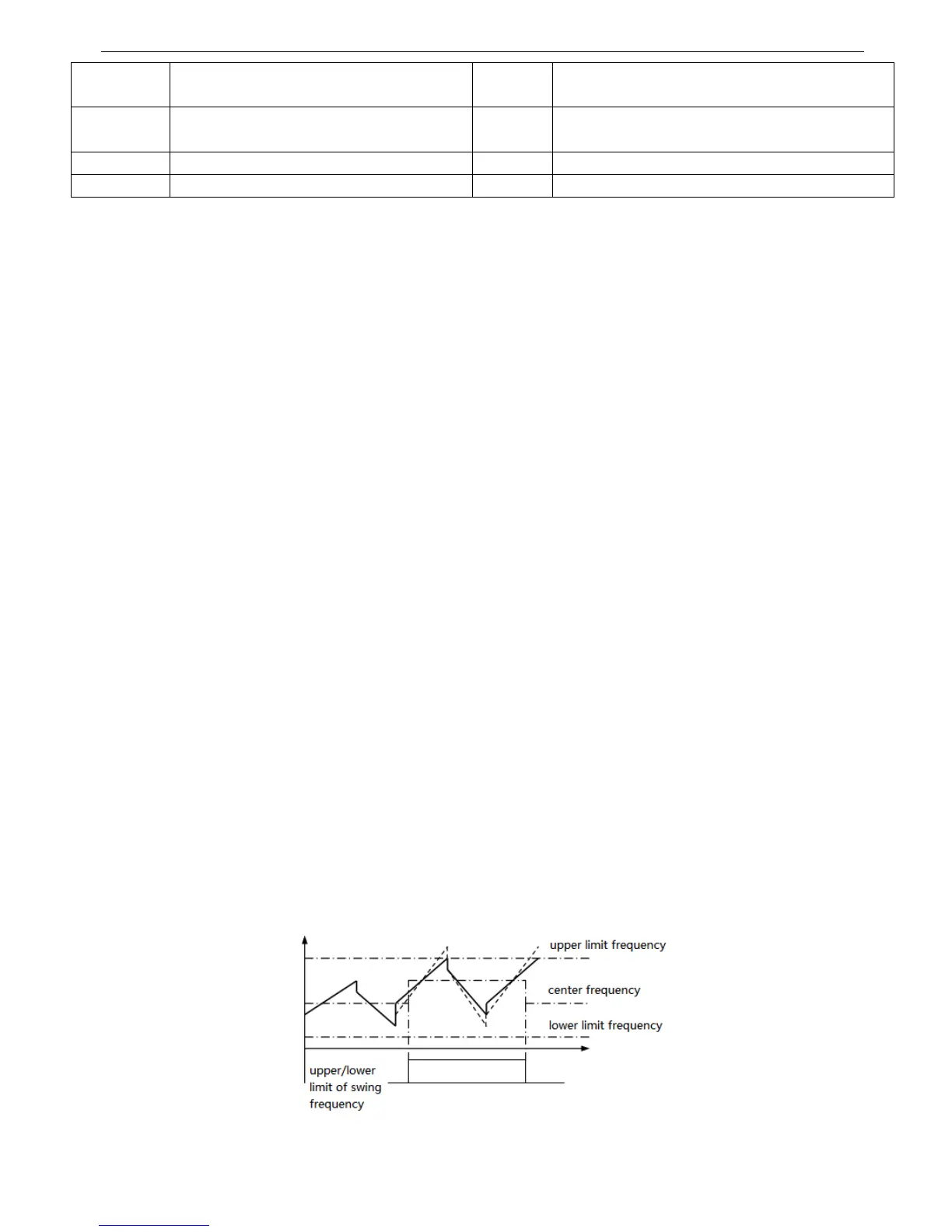
19: Upper and lower limit of swing frequency. An indicate signal will be output if the swing frequency range calculated
by center frequency exceeds the upper/lower limit frequency. See Fig 4-25.
Fig.4-25 Upper and lower limit of swing frequency