V5 series inverter
71
20: Reach the setting running time.When the accumulating running time(P3.40)arrive the setting time (P3.39), an
indication signal will be output.
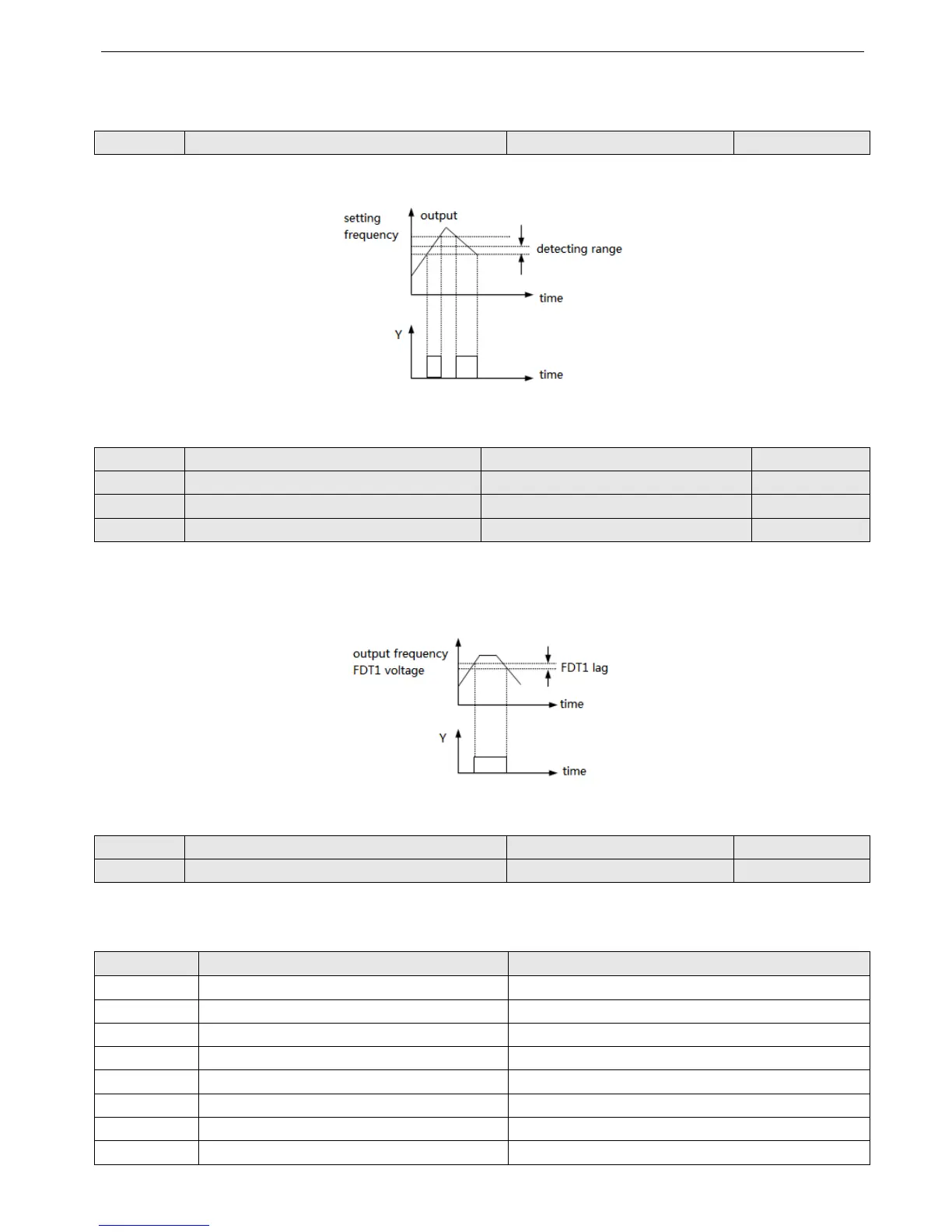
P4.12 Detecting range of frequency arrive (FAR) Range: 0.00~50.00Hz 5.00Hz
This parameter is the additional definition of No. 1 function in Table 4-6. As shown in Fig.4-26, when the output frequency
of inverter is in the detecting range of setting frequency, pulse signal will be output.
Fig 4-26 Frequency arriving signal
P4.13 FDT1 (frequency level) voltage Range: 0.00~upper limit of frequency 10.00Hz
P4.14 FDT1 lag Range: 0.00~50.00Hz 1.00Hz
P4.15 FDT2 (frequency level) voltage Range: 0.00~upper limit of frequency 10.00Hz
P4.16 FDT2 lag Range: 0.00~50.00Hz 1.00Hz
P4.13~P4.14 is the additional definition of No.2 function in Table.4-6, P4.15~P4.16 is the additional definition of No.3
function in Table.4-6, their using method are the same. The following takes P4.13~P4.14 as an example to introduce.When
the output frequency is over one frequency(FDT1 voltage), indication signal will be output until the output frequency de-
creasing below one frequency of FDT1(FDT1 voltage-FDT1 lag), as shown in Fig. 4-27.
Fig.4-27 FDT level
P4.17 Analog output selection (AO) Range: 0~7 0
P4.18 Analog output gain (AO) Range: 0.50~2.00 1.00
Table 4-7 Output terminals
No. Function Range
0 Output frequency 0~upper limit frequency
1 Output current 0~2 × rated current
2
Output voltage 0~1.2 × rated voltage of load motor
3
Bus voltage 0~800V
4
PID setting 0~10V
5
PID feedback 0~10V
6 VI 0~10V
7 CI 0~10V/4~20mA