V5 series inverter
72
For analog output AO, you can adjust the output gain to change the measuring range or calibrate the meter.
P4.19 AO output mode Range: 0, 1 1
0: 4 ~20mA
1: 0 ~10V
P4.20 DO output terminal Range: 0~120 0
Refer to Table 4-7 and 4-6 for function selection of DO output terminal.
P4.21 DO max pulse output frequency Range: 0.1~20.0 (max 20K) 10.0K
This parameter defines the max output frequency of DO terminal.
P4.22 Counter value setting Range: P4.23~9999 0
P4.23 Middle counter value setting Range: 0~P4.22 0
P4.22, P4.23 are the additional definition of No.12, 13 functions in table 4-6.
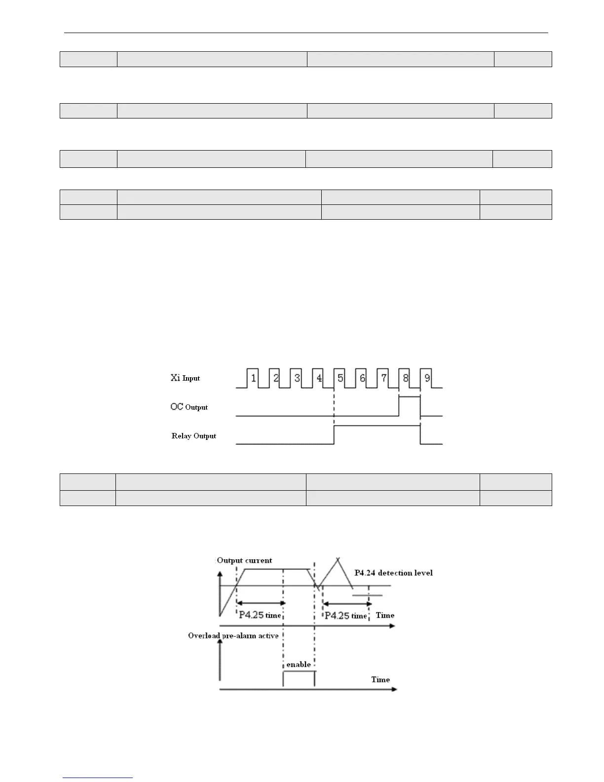
Counter value setting: when Xi receives certain quantity pulses, OC or relay will output a indicator signal.
For example: as shown in Fig. 4-28, when the eighth pulse is received by terminal Xi, OC outputs an indicating signal and
P4.22=8.
Middle counter value setting: When Xi receives certain quantity pulses, OC or relay will keep output a signal until the
counter value arrives.
As shown in Fig. 4-28, when Xi receives the 5th pulse, the realy outputs an indication signal. It keeps outputting until
counter value 8 arrived. At this time, P4.23=5. The middle counting value will be disabled if it is bigger than preset count-
ing value.
Fig.4—28 Preset counting value arrived and Middle counting value arrived
P4.24 Overload pre-alarm detection level Range: 20~200 (%) 130(%)
P4.25 Overload pre-alarm delay time Range: 0.0~20.0s 5.0s
If output current is over the current detecting level P4.24 continuously (Actual detecting current level=P4.24×inverter’s
rated current), Bi-direction open-collector will output valid signal (refer to Fig.4-29 and P4.11 for details).
Fig.4-29 Overload pre-alarm