18
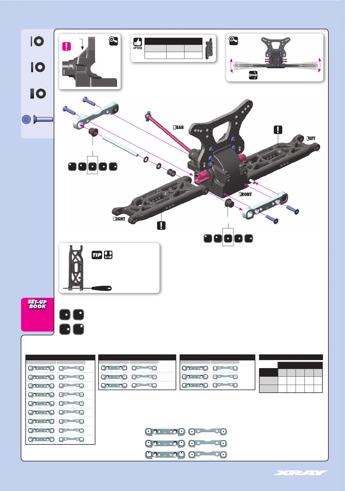
3. FRONT SUSPENSION
KICK UP
ROLL CENTER
TRACK-WIDTH
The tables describe the amounts of adjustment using the center and outside positions of the eccentric bushings.
The middle position eccentric bushings allow for finer adjustment increments.
The track-width is directly influenced by the size of the
wheels and tires used.
Example:
KICK-UP
TRACK-WIDTHROLL CENTER
FF
FFFF
FR
FRFR
(°)
(mm) (mm)
=9°
=8°
=10°
=8°
=7°
=9°
=10°
=9°
=11°
=
+
0.75mm
=
0mm
=
-
0.75mm
=
+
1.5mm
=
0mm
=
-
1.5mm
KICK-UP
C-HUB CASTER
7° 8° 9° 10° 11°
6° 13° 14° 15° 16° 17°
9° 16° 17° 18° 19° 20°
Caster is the angle between the steering pivot
axis and the vertical plane. Caster is affected not
only by the C-Hub caster, but also by the front
kick-up angle relative to the flat chassis bottom.
The table indicates how kick up angle effects
total caster.
The XT4’s stock caster blocks are 9°, but 6°
blocks are available as an option.
TOTAL CASTER
=
C-HUB CASTER
+
KICK UP
0(FF) - 0(FR) = 9°
0.5(FF) - 0(FR) = 9.5°
1(FF) - 0(FR) = 10°
= 9°
= 9.5°
= 10°
The XRAY alu front lower suspension holders provide great range of adjustment for the front suspension. Using different combinations of eccentric bushings, fine adjustment of front kick-up, roll-center, and front
track-width can be obtained. For more information about the influence of kick-up, front track-width, and roll centers on car handling, please refer to HUDY Set-up Book (#209100).
➊
➊
➋
➌
➌
➍
➍
FR
FF
Composite eccentric bushings
INITIAL POSITION
1º 1º0.5º 0.5º0º
1º
Composite eccentric bushings
INITIAL POSITION
1º 0.5º 0.5º0º
Check for free movement
903312
SFH M3x12
If the suspension arm does not move freely use a
HUDY Arm Reamer to size the holes of the arms
Arm Reamer 3.0mm
(HUDY #107633)
ECCENTRIC BUSHINGS HAVE TWO DIFFERENT OFFSETS FROM THE CENTER.
Middle position = 0.5° or 0.375mm from center.
Outer position = 1° or 0.75mm from center.
3x6x1mm
3x6x0.5mm
3x6x2mm (2x)
DETAIL
DETAIL
Marked “F”
306219
SHIM 3x6x2
306219
SHIM 3x6x1
303121-K
SHIM 3x6x0.5
SUSPENSION ARMS
#322112-M MEDIUM INCLUDED
#322112-G GRAPHITE OPTION
NOTE ORIENTATION
NOTE ORIENTATION