10
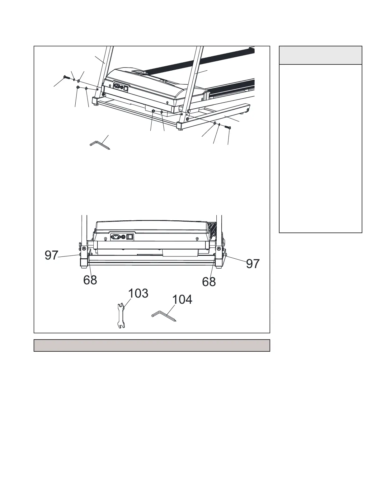
ASSEMBLY STEP 3
4
3
96
96
98
79
98
79
94
95
94
95
104
2
1. Insert the UPRIGHTS (L3, R4) into the FRAME BASE (2) and
using the COMBINATION WRENCH AND SCREWDRIVER
(#104) secure with 2 FLAT HEAD SOCKET BOLTS (#96), 2
SPLIT WASHERS (#98) and 2 FLAT WASHERS (#79). You will
also need to secure the UPRIGHTS with 2 BUTTON HEAD
BOLTS (#94) and 2 CURVED WASHERS (#95). Leave the bolts
loose and do not overtighten.
2. Secure 2 BUTTON HEAD BOLTS (#97) and 2 NYLOC NUTS
(#68) using the 13/15mm WRENCH (#103) and COMBINATION
WRENCH AND SCREW DRIVER (#104). Tighten all bolts, but
do not overtighten.
HARDWARE
2 Bolt (#96)
2 Split Washer (#98)
2 Flat Washer (#79)
2 Button Head Bolts
(#94)
2 Curved Washer (#95)
2 Button Head Bolts
(#97)
2 Nyloc Nuts (#68)
NOTE: this step may work better with a second person assisting.
 Loading...