© Copyright. Not to be reproduced without the permission of Xtrac Ltd.
1. Introduction / Scope
This standard exists to provide recommendations on tightening torques and minimum lengths of thread
engagement.
2. Tightening Torques
Please note: In all applications, Loctite 270 thread lock shall be used when assembling studs into casings.
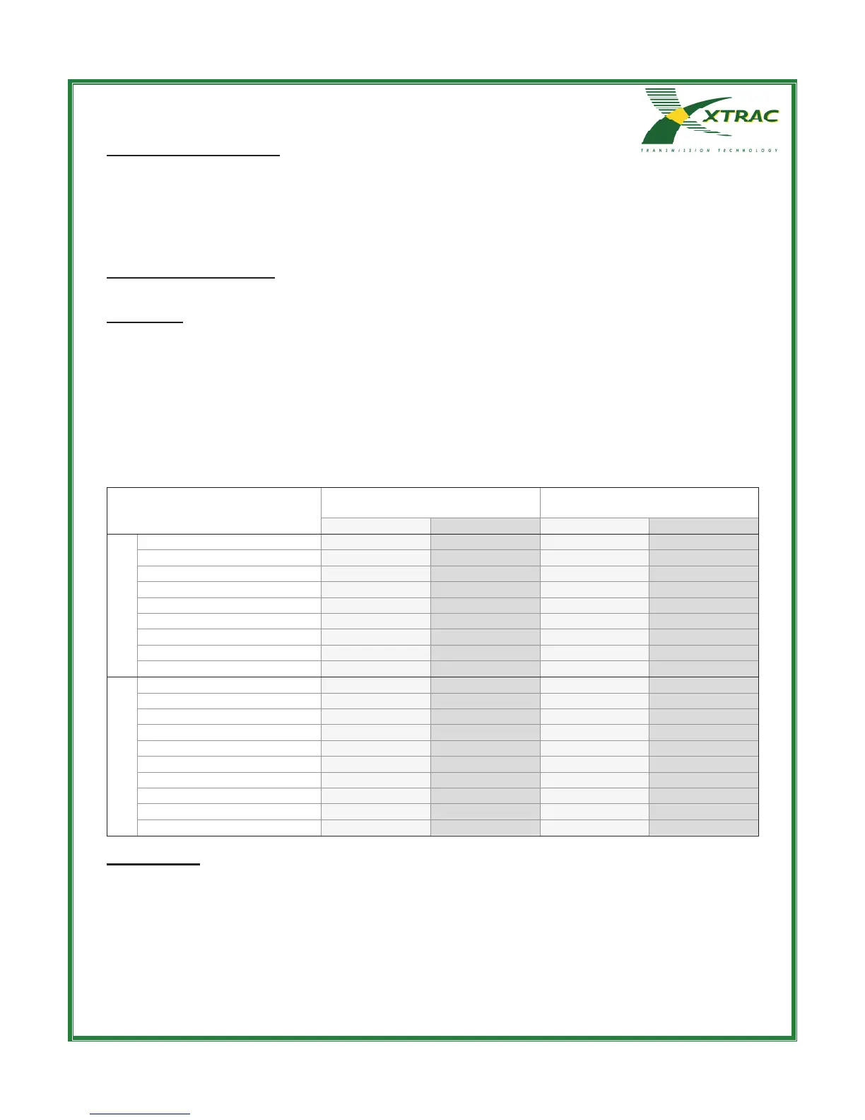
When defining tightening torques for studs into casings the torque used shall never exceed the nut tightening
torque specified in the table below. Torque figures stated are for tightening of nut onto stud, or bolt into casing.
The torque values are not for use when tightening bottom fitting studs, shank fitting studs or thread inserts directly
into the casing thread.
For all other applications, consideration should be given to the individual installation and a suitable tightening
torque should be calculated using Xtrac program AE-5148, (available from the intranet in Reference Document /
Verification Tools), and recorded as design verification against the assembly concerned.
METRIC
M4 x 0.7 3 2 3 2
M5 x 0.8 7 5 6 4
M6 x 1.0 11 8 10 7
M7 x 1.0 18 13 15 11
M8 x 1.25 26 19 22 16
M10 x 1.25 52 38 45 33
M10 x 1.5 50 37 44 32
M12 x 1.5 87 64 76 56
M12 x 1.75 85 63 74 55
IMPERIAL
1/4" UNF 13 10 11 8
1/4" UNF/UNC* 11 8 10 7
5/16" UNF 26 19 22 16
5/16" UNF/UNC* 23 17 20 15
3/8" UNF 45 33 40 30
3/8" UNF/UNC* 40 30 35 26
7/16" UNF 71 52 62 46
7/16" UNF/UNC* 64 47 55 41
1/2" UNF 106 78 92 68
1/2" UNF/UNC* 94 69 82 60
Notes on table:
*Assumes UNF nut onto Steel or Titanium stud with UNC thread into Aluminium or Magnesium Alloy,
All torque figures are based on calculations to give a safety factor of 2 when comparing the thread stress
to the 0.2% proof stress of the material. The stress calculations were derived from the Machinery's
Handbook 26, page 1482 and 1483. A friction coefficient of 0.12 was used. The inside and outside
diameters of the bearing surface contact areas were extracted from Xtrac Standard XS006, XS007,
XS008 and XS009.