3
INSTALLATION
FILTER LOCATION
It is important to rst determine where your pump and lter will be located. If above the water line.a self-
priming pump must be used. Self-priming pumps have the ability to lift water from a lower level and prime
automatically.
1. Since plumbing ttings offer a resistance to water ow, position the lter as close to the swimming pool
as local codes allow. Keep the number of ttings to a minimum. Select a well drained area, one that will not
ood when it rains.
2. Set the lter on a solid , level surface. Be sure lter, pump, drain and pressure gauge are accessible for
convenient operation.
3. Position the lter so the tank can drain by gravity.
4. lf practical.place pump and lter in the shade to shield it from continuous.direct heat from the sun
PLUMBING
1. Use 1-1/2” or 2”piping. When making permanent connections, be sure to provide unions for easy servicing.
2. Refer to the diagrams for basic suggested valving. Ballvalves are recommended where needed. While all
systems vary, lrle main consideration is to provide the desired control of water ow from the pool to the pump
and lter, and back to the pool. When the lter IS located below water level, provide valves to prevent back
ow of water to the lter during cleaning and routine servicing.
3. All plumbing on the Star-Clear Plus lter are 1-1/2” or 2”N.P.T. or socket (solvent weld). When making
threaded connections to the lter use plastic adapters. Apply three turns of Teon tape (or use special plastic
pipe sealant) to male threads. Screw the tting into the thread hand tight: then using a wrench, tighten one
more full turn. Additional tightening is unnecessary.
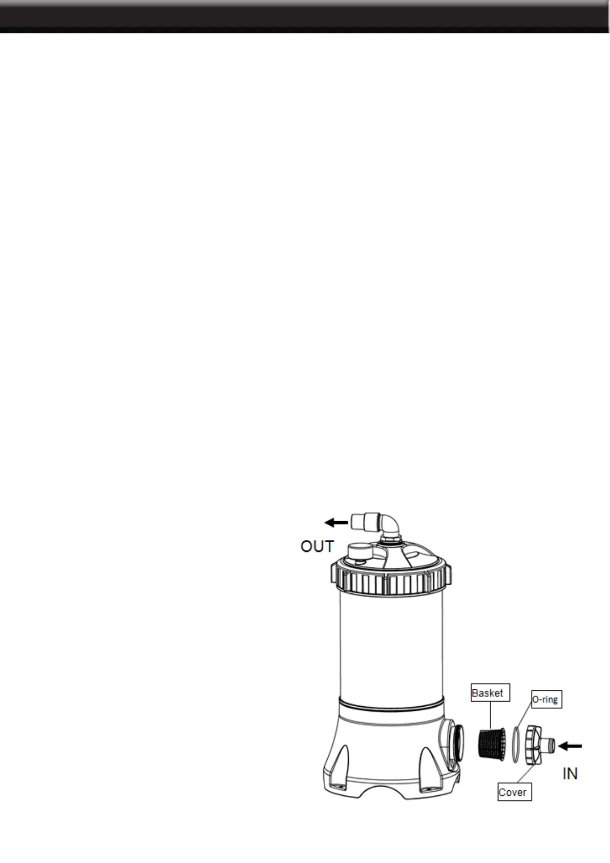
4. Install pre-lter, o-ring and clear cover on the inlet as below illustration.
5. Connect the pool suction plumbing between
the skimmer, pool outlet, etc. and the pump.
6. Install the pool return plumbing.
7. If pressure gauge IS not Installed, apply
Teon tape to the gauge threads, and
carefully screw the gauge into the threaded
hole in the lter head.
8. A manual air relief valve is
furnished to aid in bleeding off unwanted
air when starting the lter. The auto air relief
provides air removal during operation.
9. All electrical connections should be made
In accordance with local codes.
10. Check for joint leaks before operating.
11. Refer to pump instruction booklet for
pump information.
 Loading...