Do you have a question about the Yaesu FT-747GX and is the answer not in the manual?
Details frequency ranges, emission types, and power output.
Covers frequency range, circuit type, sensitivity, and selectivity.
Includes tuning steps, frequency stability, accuracy, and impedance.
Lists standard and optional accessories with part numbers.
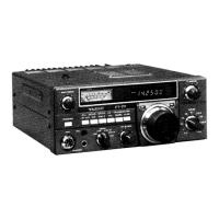
Introduces and details front panel controls and their functions.
Explains the pushbutton switch for turning the transceiver on and off.
Describes the 8-pin connector for microphones and scanning controls.
Details the jack for connecting monaural or stereo headphones.
Explains how to use the clarifier for receiver tuning offset.
Describes the button to prevent accidental frequency changes.
Explains tuning steps and the FAST button for mode-dependent tuning.
Details how to change frequency bands using 500 kHz steps.
Describes AF gain for volume and squelch for noise muting.
Explains MIC gain for transmit audio and DRIVE for power output.
Details MODE, VFO-M, M-VFO, VFO/MR, and SPLIT keys.
Explains the NAR button for selecting narrow IF filters in CW/AM.
Describes the 20dB attenuator for receiver protection and sensitivity adjustment.
Details the noise blanker for reducing pulse-type interference.
Details the button for manually switching between transmit and receive.
Explains the meaning of various indicators on the transceiver display.
Describes the red lamp that glows when transmitting.
Explains the meter for showing signal strength and power output.
Details the recessed trimmer capacitors for IF passband center offset.
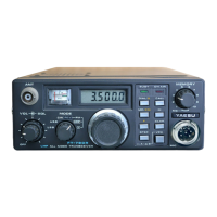
Describes the phono jack for powering accessories with 13.5V DC.
Explains the 1/8-inch jack for connecting an external loudspeaker.
Describes the jack for connecting a CW key or electronic keyer.
Details the phono jack for constant low-level receiver audio output.
Explains the phono jack for automatic level control from a linear amplifier.
Describes the phono jack for external transmit/receive switching.
Details the 8-pin DIN connector for bandswitching signals.
Explains the 4-pin connector for 12-15V DC power input.
Describes the type-M SO-239 jack for antenna system connection.
Details the terminal for connecting to a good earth ground.
Explains the 6-pin DIN jack for computer control via serial data.
Guides on inspecting the transceiver for damage upon unboxing.
Covers power supply requirements and connection for base station use.
Advises on optimal placement and proper grounding for performance and safety.
Details antenna impedance and SWR considerations for optimal operation.
Explains surge suppression and lamp fuse protection for the receiver.
Provides instructions for connecting power in vehicles, emphasizing battery connection.
Describes the use of the optional mounting bracket for vehicle installation.
Offers guidance on mobile antenna placement and grounding.
Details how to connect linear amplifiers and optional relay boxes.
Explains the internal lithium cell for memory retention and backup circuit control.
Guides on initial setup and basic receiving operations.
Explains how to select operating bands using the BAND button and tuning knob.
Details how to choose between LSB, USB, CW, AM, and FM modes.
Covers using the tuning knob, FAST button, and D LOCK for frequency adjustment.
Provides instructions for receiving SSB signals, including ATT, NB, and SQL controls.
Explains when and how to use the 20dB attenuator for strong signals.
Details the noise blanker for reducing pulse-type interference.
Guides on setting the squelch threshold to silence receiver noise.
Covers CW reception with narrow filters and tuning tips.
Explains AM reception, narrow bandwidth, and Exalted Carrier Selectable Sideband.
Details FM reception, noting the optional FM unit and key settings.
Covers setup for RTTY and packet using external TU/TNC.
Introduces transmitter operation, power settings, and precautions.
Guides on setting up and performing SSB transmissions.
Explains how to use the clarifier for tuning receiver frequency independently.
Details CW transmission with semi break-in and power adjustment.
Covers FM transmission, noting disabled controls and power adjustment.
Guides on adjusting MIC gain and DRIVE for AM transmission.
Details AFSK input and transmission for RTTY, packet, and SSTV.
Explains how to store, recall, and manage frequencies and modes in memory.
Describes how to select between VFO A and VFO B for operation.
Explains how to switch between VFO and memory operation.
Details the procedure for saving VFO data into a memory channel.
Guides on retrieving stored frequencies and modes from memory.
Explains how to update memory data by shifting it to a VFO.
Details how to set up and use split frequency operation with two VFOs.
Guides on activating and using the memory scanning feature.
Explains how to select specific memories to be skipped during scanning.
Describes monitoring a VFO while periodically checking a memory channel.
Provides step-by-step instructions for removing the transceiver's top cover.
Explains how to change the AGC decay setting for different modes.
Details switch settings for controlling transmission with external devices.
Guides on installing the optional FM Unit into the transceiver.
Explains how to install the Temperature Compensated Crystal Oscillator for improved stability.
Describes the serial data format for transmitting individual characters.
Explains the 5-byte block structure for CAT commands and data.
Details the meaning of bits within the Status Flags byte.
Explains the 5-byte format for representing operating frequency.
Guides on using UPDATE and PACING commands to retrieve status.
Outlines the structure and mapping of transceiver status data.
Lists available CAT instruction opcodes and their parameters.
Provides a map detailing the location and description of status update data bytes.
| Brand | Yaesu |
|---|---|
| Model | FT-747GX |
| Category | Transceiver |
| Language | English |