EasyManuals Logo

Yaesu FT-747GX Technical Supplement

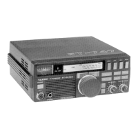
Yaesu FT-747GX
26 pages
To Next Page IconTo Next Page
Page #1 background imageLoading...
Page #1 background image
CONTENTS
TOP
COVER
БЕМОУА!,..........................
EXPLODED
VIEW...
û
ea
ee
eee
eee
eee
eee
eee
eee,
MAIN
UNIT
asyl
иа
шки
кива
н
ро
Circuit
Diagram
FILTER
UNIT
а...
жк
eee
e
s
ашы
ыы
Circuit
Diagram
NB
UNIT
Circuit
Diagram
LOCAL
UNIT
........
TELETELE
Parts
Layout
Circuit
Diagram
HOW
PA
UNIT.......
3
A
e
бю
чай
00
SQ
Parts
Layout
Circuit
Diagram
LPF
UNIT
EE
EEE
o
ESS
Parts
Layout
Circuit
Diagram
DISPLAY
UNIT
ж
аа
невин
ка
aan
Parts
Layout
Circuit
Diagram
CONNECTION
DIAGRAM
.........................
LEVEL
DIAGRAM
.........................
9
|
Transmit
|
Е
Receive
SIGNAL
РАТИ
4
5
єє.
š
$
woa
siw
w
e
o]
шаан
BSBUMODE
ааа
а
ааа
CW
MODE
fm
deve
ала
$544
FU
шшш
A
АМ
МОРЕ
ER
ERE
SSE
bee
оваа
ааваа
FM
MODE
MR
а
ШЕ
АШЫ
duse
av
d
S.
een
ALIGNMENT
....«..«««є«ичїїї
ios.
me
ropa
L
Local
Unit
|
II.
Main
Unit
-
Receiver
III.
Main
Unit
-
Transmitter
IV.
Noise
Blanker
Unit
V.
100W
PA
Unit
(Idling
Current)
VI.
LPF
Unit
(CM
Coupler
Balance)
VII.
Main
Unit
(AFP
-
Automatic
Final
Protection)
PARIS
UST
aurora
rra
rr
FT-747GX
TECHNICAL
SUPPLEMENT
This
manual
is
intended
to
serve
as
a
supplement
to
the
FT-747GX
Operating
Manual.
De-
tailed
information
regarding
functions,
installation,
interconnections
and
operation
has
been
provided
in
the
Operating
Manual,
and
is
not
reprinted
herein.
Therefore,
this
supplement
is
not
intended
to
serve
as
an
independent
reference,
but
to
be
used
in
conjunction
with
the
information
provided
in
the
Operating
Manual.
Because
there
are
nearly
two
hundred
and
fifty
semiconductor
devices
in
the
FT-747GX,
circuit
description
information
is
provided
in
the
form
of
numerous
block
diagrams.
We
hope
that
this
manner
of
providing
functional
information
proves
to
be
more
convenient
for
the
owner
and
technician
than
would
a
lengthy
verbal
description.
Those
readers
unfamiliar
with
the
basic
types
of
analog
and
digital
circuits
that
serve
as
the
building
blocks
of
the
FT-
747GX
are
encouraged
to
study
instructional
material,
such
as
that
provided
in
handbooks
on
amateur
radio
and
digital
circuit
design,
before
attempting
to
understand
the
design
of
the
FT-747GX.
Each
block
in
the
block
diagrams
represents
one
such
basic
circuit.
General
infor-
mation
on
integrated
circuits
and
their
applications
is
available
in
the
data
provided
by
the
IC
manufacturers.
Specific
circuit
details
are
provided
in
the
schematic
diagrams
in
this
manual.
While
we
believe
the
technical
information
in
this
manual
is
correct,
Yaesu
assumes
no
liability
for
damage
that
may
occur
as
a
result
of
typographical
or
other
errors
that
may
be
present.
Your
cooperation
in
pointing
out
any
inconsistencies
in
the
technical
information
would
be
appreciated.
Yaesu
Musen
reserves
the
right
to
make
changes
in
the
circuitry
of
this
transceiver,
in.
the
interest
of
technological
improvement,
without
obligation
to
notify
owners
or
to
modify
any
sets
produced
prior
to
the
modification.

Other manuals for Yaesu FT-747GX

Questions and Answers:

Question and Answer IconNeed help?

Do you have a question about the Yaesu FT-747GX and is the answer not in the manual?

Yaesu FT-747GX Specifications

General IconGeneral
BrandYaesu
ModelFT-747GX
CategoryTransceiver
LanguageEnglish

Related product manuals