Do you have a question about the Yaesu FT-790R and is the answer not in the manual?
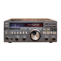
General operating parameters, frequency coverage, and physical characteristics.
Transmitter performance characteristics, power output, and suppression.
Receiver sensitivity, selectivity, audio output, and frequency response.
List of semiconductor components utilized in the transceiver's design.
List of optional or included accessories for the FT-790R.
Main dial, step selection, VFO, and mode controls for operation.
MR/PRI, F, M, and MEMORY switches for memory and function management.
SQL and VOL controls for audio gain and noise muting.
CALL and CLAR buttons for repeater access and offset tuning.
NB, HI/LOW power, and LAMP/BATT switches on the rear panel.
Key, EXT DC 13.8V, and CHG jacks on the rear panel.
Mechanism for easily opening the transceiver cabinet for battery access.
STAND BY and EXT SP jacks for external devices.
TONE SQ., SCAN, COMP, and BACKUP internal switches.
Pre-operation checks for batteries, power source, and connections.
Explanation of the digital LCD frequency display and its indicators.
Description of the receiver section's signal path and key components.
List of necessary test equipment for performing alignment procedures.
Procedure to set the 5.7 VDC voltage level.
Procedure to check battery voltage and calibrate the meter.
Alignment of the PLL local oscillator and IF stages.
Alignment of the Voltage Controlled Oscillator (VCV) line.
Alignment of the FM Intermediate Frequency and detector stages.
Alignment of the SSB Intermediate Frequency and Radio Frequency stages.
Alignment of exciter stages and adjustment of idling current.
| Weight | 1.5 kg |
|---|---|
| Voltage | 13.8 V DC |
| Frequency Range | 144-148 MHz |
| Mode | FM |
| Receiver Sensitivity | 0.2 µV for 12 dB SINAD (FM) |
| Dimensions | 140 x 40 x 180 mm |