Do you have a question about the Yaesu FT101-EE and is the answer not in the manual?
Details the SSB, CW, and AM modes, power input, and frequency range.
Describes transistorized circuits, plug-in modules, and self-contained design.
Covers AC/DC operation, mobile setup, and heater switch.
Lists VOX, calibrators, noise blanker, WWV, and clarifier.
Details weight, dimensions, and optional accessories.
Specifies frequency range, type of emission (SSB, CW, AM).
Lists power input, carrier/sideband suppression, spurious radiation.
Details frequency stability, sensitivity, selectivity, and impedance.
Covers audio output, power consumption, dimensions, and weight.
Guidance for connecting power and ground for base operation.
Covers 12V DC operation, mounting, wiring, and safety.
Specifies antenna impedance and matching.
Illustrates how external units connect to the transceiver.
Details the wiring for microphone connections.
Describes VFO selection switch and MODE switch functions.
Explains RF/AF gain, tuning knob, and band switch.
Details the clarifier control for receiver frequency adjustment.
Describes preselector, mic gain/carrier, plate, loading, level controls.
Explains power, heater, MOX-PTT-VOX switch functions.
Details process, noise blanker, RF attenuator, calibrator switches.
Describes headphone jack, microphone input, and meter selection.
Lists AF-IN, IF OUT, SP, REC, TONE, A-TRIP, RCV ANT jacks.
Details PTT, PATCH, FAN, ACC, KEY, EXT VFO, POWER jacks.
Covers GND, LAMP FUSE, ANT, and FUSE connections.
Covers initial checks, voltage verification, and frequency reading.
Steps for calibrating the receiver using the calibrator signal.
Initial adjustments for transmitter tuning (bias, ALC).
Procedure for maximizing transmitter output power.
Details SSB operation and RF processor usage.
Explains CW and AM operation procedures.
Describes the function of various circuit units like AF, IF, RF.
Lists the transistors, ICs, and tubes used in the unit.
Details the HF unit circuitry, including mixers and oscillators.
Describes the HF IF unit, mixers, and bandpass networks.
Details the LF IF unit, filters, detector, and AGC circuits.
Provides instructions for installing an optional CW filter.
Details the audio unit, including microphone amp and VOX.
Describes the modulator unit with carrier oscillators and ring modulator.
Details the voltage regulator circuit for stable DC supply.
Explains the 100 KHz/25 KHz marker generator for calibration.
Details the VFO unit for frequency generation and tuning.
Explains the noise blanker circuit for reducing noise pulses.
Describes crystal control and RF processor functions.
Details the rectifier unit providing DC voltages.
Describes main chassis components like power supply and preselect.
Explains the driver and final power amplifier stages.
Details meter functions for signal strength and power output.
Provides step-by-step instructions for installing the CW filter.
Explains formula and table for calculating crystal frequencies.
Provides safety warnings and general alignment overview.
Lists necessary test equipment for alignment procedures.
Procedure to adjust S-meter sensitivity.
Procedure to adjust noise blanker threshold.
Steps for adjusting VOX gain, delay, and sensitivity.
Alignments for CW sidetone, carrier balance, and ALC level.
Alignment steps for RF processor and voltage regulator.
Procedures for aligning clarifier and adjusting bias.
Procedure to adjust the power output meter indication.
Steps for neutralizing the final amplifier tubes.
Aligning transmitter mixer and driver stages.
Aligning the receiver front end stages.
Tuning procedures for the 80 meter band.
Tuning procedures for the 40 meter band.
Tuning procedures for the 160 meter band.
Checking the local oscillator injection voltage.
Chart for tuning capacitors and crystal frequencies.
Adjusting trap coils T107, L29, L22.
Aligning T113, T115, L28, TC30 for radiation suppression.
Table showing DC voltages for each pin.
Table showing RF voltages for each pin.
Table listing resistance values for circuit units.
Lists resistors, capacitors, and inductors for the RF unit.
Lists diodes, variable resistors, and trimmers for the RF unit.
Lists components for the AF unit (PB1315A).
Lists components for the Mod & Osc unit (PB1184A).
Lists components for PB-1534 and PB-1292 units.
Lists components for the VFO unit (PB-1056).
Lists various component types like trimmers, jacks, and crystals.
Lists components for the Rectifier unit (PB-1076).
Lists system components like switches, relays, fuses, and lamps.
Provides crystal frequencies and band data.
Schematic diagram for the AF unit.
Schematic diagram for the VFO unit.
Schematic diagrams for IF and Noise Blanker units.
Schematic diagram for the Fix & Process unit.
Schematic diagrams for RF and Drive units.
Schematics for RF trimmers and amplifiers.
Schematic diagrams for Power Amplifier and Power Supply units.
| Brand | Yaesu |
|---|---|
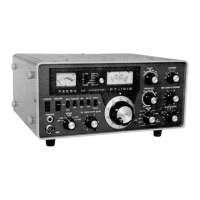
| Model | FT101-EE |
| Category | Transceiver |
| Language | English |