EasyManua.ls Logo

Yaesu G-650A User Manual

Yaesu G-650A
15 pages
To Next Page IconTo Next Page
Page #1 background imageLoading...
Page #1 background image
G-450A
G-650A
Antenna Rotator & Controller
User Manual
YAESU MUSEN CO., LTD.
1-20-2 Shimomaruko, Ota-Ku, Tokyo 146-8649, Japan
YAESU U.S.A.
17210 Edwards Rd., Cerritos, CA 90703, U.S.A.
YAESU EUROPE B.V.
Snipweg 3, 1118DN Schiphol, The Netherlands
YAESU UK LTD.
Unit 12, Sun Valley Business Park, Winnall Trading Estate
Winchester, Hampshire, SO23 0LB, U.K.
YAESU GERMANY GmbH
Am Kronberger Hang 2, D-65824 Schwalbach, Germany
YAESU HK LTD.
11th Floor Tsim Sha Tsui Centre, 66 Mody Rd.,
Tsim Sha Tsui East, Kowloon, Hong Kong
Question and Answer IconNeed help?

Do you have a question about the Yaesu G-650A and is the answer not in the manual?

Yaesu G-650A Specifications

General IconGeneral
Control TypeDigital
Control MethodManual and Automatic
TypeRotator Controller
CompatibilityYaesu G-650A
Rotation Range450 degrees
Mast SizeUp to 60 mm diameter
Power Consumption60 VA
WeightApprox. 3.6 kg

Summary

Packing List

Specifications

Installation/Operation Precautions

Controller Front/Rear Panel Controls and Switches

Controller Front Panel

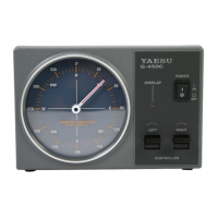
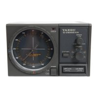
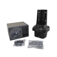
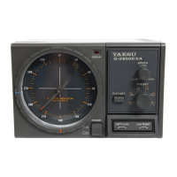
Describes controls and indicators on the front of the controller unit.

Controller Rear Panel

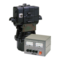
Details controls and connections found on the rear of the controller unit.

Rotator Unit Components and Dimensions

Rotator Attachment Plate Dimensions

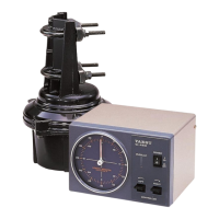
Specifies the dimensions and drilling pattern for the rotator's mounting plate.

Which Antennas Can Be Attached?

Pole-Mounted Antennas

Guidelines for attaching antennas when mounting the rotator on a pole.

Tower-Mounted Antennas

Specifications for antenna attachment when mounting on a tower.

Control Cable Installation

Control Cable Preparation

Step-by-step instructions for preparing the control cable for connection.

Assembly of 6-pin Plastic Connector

Guide for assembling the 6-pin plastic connector for the control cable.

Assembly of 7-pin Metal Connector

Guide for assembling the 7-pin metal connector for the control cable.

Wiring for the control cable

Details the wiring scheme for the control cable connections.

Mounting the Rotator and Antenna

Indoor Performance Check and Alignment

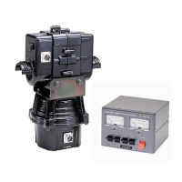
Procedure for checking and aligning the rotator system before final installation.

Installation of Rotator and Antenna on Tower

Installation Note

Important considerations for installing the rotator on a roof tower with a long mast.

Important Safety Information

Related product manuals