Do you have a question about the Yaesu G-800DXA and is the answer not in the manual?
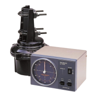
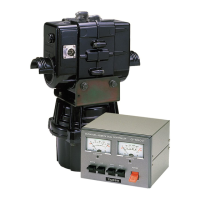
Details the clamshell design, ball bearings, and DC motor for durability and low stress.
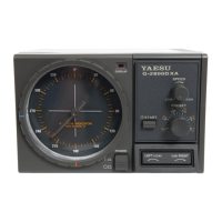
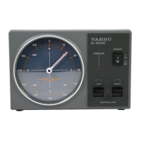
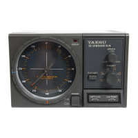
Highlights the 360° azimuth indicator, variable speed, and preset heading capabilities.
Explains 'auto slow start' and 'auto slow stop' features for the G-2800DXA model.
Advises on tower mounting and optional thrust bearings like GS-680U.
Introduces the optional GS-232B Computer Control Unit for PC operation.
Details the function of the POWER switch to turn the controller on or off.
Explains using the seesaw switch for counter-clockwise (LEFT) and clockwise (RIGHT) rotation.
Describes setting a desired heading and activating automatic rotation with START.
Explains how to set the desired rotating speed for the antenna.
Details the LED indicator for rotation beyond 180° and its implications.
Describes the 6-pin mini-DIN connector for the GS-232B Computer Control Unit.
Explains the SELECT SWITCH for ADJ. MODE and OPERATION MODE.
Calibrates the maximum rotation angle of the azimuth indicating needle.
Calibrates the OVERLAP Indicator LED to match the needle.
Calibrates the PRESET control angles to match the azimuth needle.
Presets voltage for A-to-D converter calibration of GS-232B.
Jack for connecting the control cable from the rotator unit.
Specifies fuse ratings and AC power connection point.
Explains the formula [Area] x [Height] for safe pole mounting.
Recommends not exceeding 60% of the maximum rating for safety margin.
Specifies maximum Wind Loading Area and 'K' factor for tower mounting.
Demonstrates calculating the total K factor for stacked antennas.
Advises keeping antenna/mast load within 60% of maximum rating.
Details required conductor diameter based on cable length (e.g., #20 AWG or #18 AWG).
Step-by-step guide to disassembling and preparing the 7-pin round plug.
Instructions for stripping wires and soldering them to the rotator end plug pins.
Guide for crimping pins and connecting wires to the rectangular controller plug.
Steps to power on the controller and test rotator direction with the seesaw switch.
Diagram showing the assembly of the 6-pin plastic connector.
Diagram for assembling the 7-pin metal connector, noting unused terminal.
Illustrates the pin-to-pin wiring for the control cable.
Connect cable, set SELECT SWITCH to ADJ. MODE, and turn on power.
Aligning the indicator needle to 180° (South) using bezel and FULL SCALE ADJ.
Checking 360° rotation, OVERLAP LED illumination, and stop points.
Calibrating PRESET ADJ A and B potentiometers for accurate stopping.
Switching SELECT SWITCH to OPERATION MODE and powering off.
Procedure for installing the clear plastic dial heading sheet for desired orientation.
Method for aligning the PRESET knob stopper if potentiometer adjustment is insufficient.
Drilling a 9 mm hole in the mast for the anti-twist support bolt.
Securing the rotator unit to the tower's mounting plate using M8 bolts.
Mounting the optional thrust bearing (e.g., GS-065) on the tower.
Attaching the mast clamp to the rotator and inserting the antenna mast.
Installing the control cable plug into the rotator's jack and securing it.
Providing sufficient slack for the coaxial cable to allow full antenna rotation.
Testing rotator operation and checking for obstructions or binding.
Recommendation for using Guy Bearings with long masts for stability.
Drilling a 9 mm hole in the mast for the anti-twist support bolt (82 mm from bottom).
Attaching the G-2800DXA rotator to the tower mounting plate.
Mounting the optional thrust bearing for the G-2800DXA.
Securing the antenna mast to the G-2800DXA rotator using mast clamps.
Connecting the control cable to the G-2800DXA rotator unit.
Ensuring adequate slack for the coaxial cable during G-2800DXA rotation.
Testing the G-2800DXA rotator's full range of operation after installation.
Guidance on using Guy Bearings with the G-2800DXA on long masts.
Introduction to the optional GS-232B unit for PC control of the rotator.
Details the function of each pin on the GS-232B interface connector.
Adjusting the OUT VOL ADJ for the rotor rotation angle detection output.
Details power supply, rotor voltage, rotation time, range, and torque for all models.
Covers maximum vertical load, braking torque, and braking type for each model.
Provides physical specs, weights, K factor, and wind loading area limits.
Lists operating temperature range and maximum continuous duty cycle.
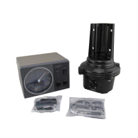
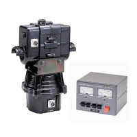
Lists items to check when unpacking the G-800DXA/G-1000DXA and G-2800DXA.
Details optional accessories like mast clamps, thrust bearings, and control units.
The Yaesu G-800DXA, G-1000DXA, and G-2800DXA are antenna rotators and controllers designed for amateur and professional antenna arrays. These systems allow for remote control of large tower-mounted antennas from a station operating position.
The core function of these devices is to rotate an antenna array to a desired azimuth. The controller provides a 360° radial indication of the actual antenna bearing. Users can select a rotating speed and preset a desired heading for automatic rotation. The G-2800DXA model includes "auto slow start" and "auto slow stop" features to prevent sharp jolts to the antenna array and tower, ensuring a gentle start and stop. The rotator allows for 90° overlapping rotation, enabling a total rotation of 450°. An optional GS-232B Computer Control Unit is available for antenna positioning via a personal computer using an RS-232 serial interface.
| Brand | Yaesu |
|---|---|
| Model | G-800DXA |
| Category | Controller |
| Language | English |