Maintenance and Repair 1300 YRM 1330
2. Tighten capscrews to 110 N•m (81 lbf ft). See Fig-
ure 17.
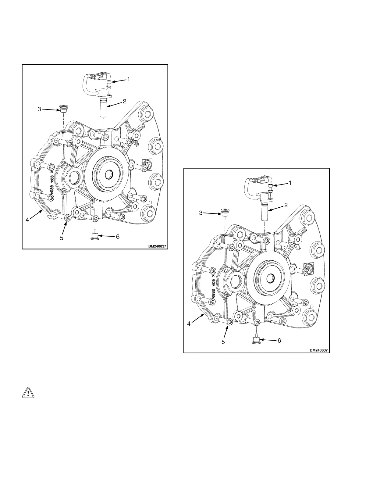
1. SOCKET-HEAD SCREW
2. SPEED SENSOR
3. FILL PLU
G
4. COVER
5. SOCKET-HEAD CAPSCREW
6. DRAIN PLU
G
Figure 17
.CoverAssembly
3. Install b
rake and traction motor on transaxle. Install
transax
le on lift truck. See section Install Transaxle
to Frame
.
4. If the le
ak persists, the unit must be reported to Yale
Company
Contact Management.
After th
e Transaxle Warranty Period
Removin
gtheCover
CAUTION
The transaxle is heavy and can be difficult to stabi-
lize when positioned with the studs down. Securely
support the transaxle in a stable position during
these procedures.
1. Remove the transaxle from the lift truck and remove
the parking brake and traction motor. See section
Remove Transaxle From Frame.
2. Drain fluid from transaxle.
3. Remove ten socket-head capscrews holding cover
on housing. See Figure 18.
NOTE: The cover is aligned to the housing with internal
components of the transaxle. Carefully pry the cover
from the housing by levering equally on each side.
4. Separate cover from housing by tapping around
seam of cover and housing using a thin flat chisel.
Gently pry around cover in small equal increments
to remove from housing.
1. SOCKET-HEAD SCREW
2. SPEED SENSOR
3. FILL PLUG
4. COVER
5. SOCKET-HEAD CAPSCREW
6. DRAIN PLUG
Figure 18. Cover Assembly
14
 Loading...