An ASSA ABLOY Group brand
80-9470-0330-000 (01-13)
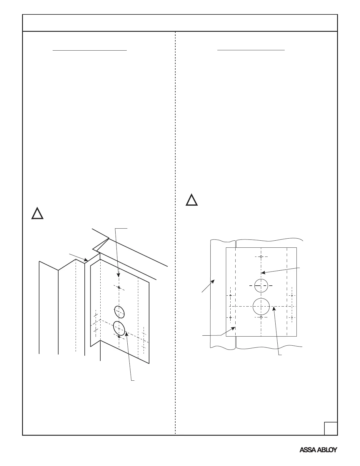
1. Frame and Door Preparation
Frame
Edge
Horizontal
Reference
Line
L
C
Out-swinging Door
In-swinging Door
DO
OR
DOOR
Frame
Frame
1. For installation on an In-swinging Door, mark a
Vertical Reference Line 1-15/16"(50mm) off of the
Frame Edge, also decide the vertical placement and
mark a Horizontal Reference Line. Align template
as shown with Vertical and Horizontal Reference Lines.
2. Use a center punch to mark door for
(2) .144"(3.7mm) Dia. (#27 Drill) mounting holes
for the Device Mounting Base (Shown Below).
3. Use a center punch to mark frame for (2) .099"(2.5mm) Dia.
(#39 Drill) holes for the Magnet (Shown Below).
4. If outside Cylinder Control Option is to be used,
bore a 1-1/4"(32mm) Dia. Hole thru door. Fig. 2 ‘B’ Hole
5. For Hardwire option requiring door preparation, mark and
bore a 1"(25mm) Dia. Hole to required depth. Fig. 2 ‘C’ Hole
6. Install Magnet to door frame with (2) #4 screws supplied.
1. For installation on an Out-swinging Door,
mark a Vertical Reference Line 2-3/16"(56mm)
off of the Frame Stop, also decide the vertical
placement on the door and mark a Horizontal
Reference Line. Fold template as shown and
align with Vertical and Horizontal Reference Lines.
2. Use a center punch to mark door for
(2) .144"(3.7mm) Dia. (#27 Drill) mounting holes
for the Device Mounting Base (Shown Below).
3. Use a center punch to mark frame for
(2) .099"(2.5mm) Dia. (#39 Drill) holes for the Magnet
(Shown Below).
4. If outside Cylinder Control Option is to be used,
bore a 1-1/4"(32mm) Dia. Hole thru door. Fig. 1 ‘B’ Hole
5. For Hardwire option requiring door preparation, mark and
bore a 1"(25mm) Dia. Hole to required depth. Fig. 1 ‘C’
Hole
6. Install Magnet to door frame with (2) #4 screws supplied.
Vertical
Reference
Line
Vertical
Reference
Line
Horizontal
Reference
Line
Figure 2
Figure 1
C
B
C
B
Arrows on the magnet face toward the
alarm housing and away from the door.
!
Arrows on the magnet face toward the
alarm housing and away from the door.
!
2