An ASSA ABLOY Group brand
80-9470-0330-000 (01-13)
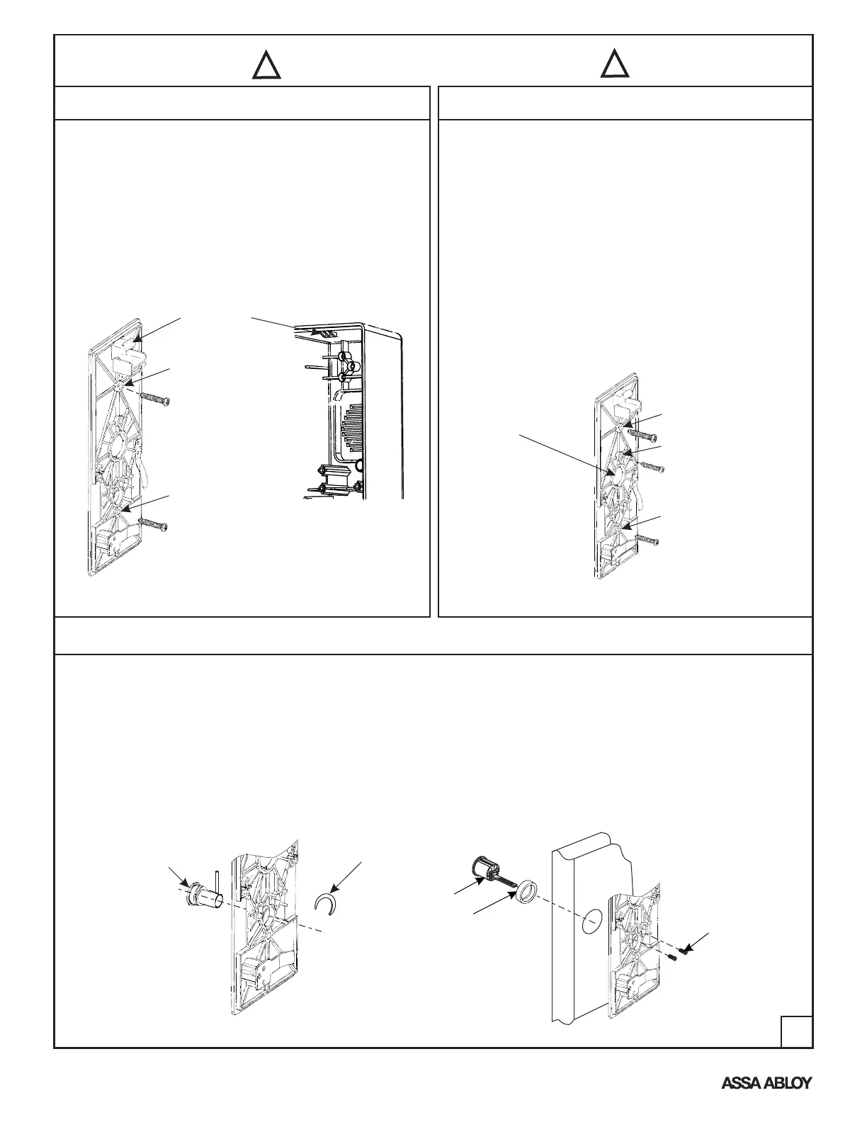
4. Standard Installation
6. Standard Device x Outside Cylinder Control Installation
3. Attach mounting base to door, wall or Gang Box following
previous instructions from Step 4 or 5.
4. With mounting base securely attached to door,
insert cylinder and ring through prep on opposite
side of door, fasten securely with (2) cylinder screws
inserted through slotted holes in the mounting base
(See Figure 10).
NOTE: Cylinder Screws and Collar are supplied with
the cylinder, when required.
5. Hardwire Installation
Note: Hardwire options require wire harness within the door or
wall and may require door position switches (DPS) or other means
of activation. This unit is equipped to accept the Electrolynx™ quick
connect system. See catalog for wiring harness and power supply
details.
1a. Door Mounted. After preparing the door, remove Knockout Plug
and attach the Mounting Base to the door through holes “A” &
“D”, using (2) #10 screws provided.
NOTE: Knockout Plug will accept standard 1/2" electrical nipple
to protect wires.
1b. Wall Mounting. This unit may be mounted between two doors,
to monitor both doors (TIP: Attach unit to a wall stud).
1c. Wall Mounting to a single “Gang Box”. Attach the Mounting
Base through holes “A” and “X”, using standard gang box
screws as shown in Figure 8 (Gang Box screws not provided).
Attach Alarm Housing per section 4.2 & 4.3 (Standard Installation).
Hole “D”
Hole “D”
Hole “X”
(*Gang Box Only)
Hole “A”
1. After preparing the door, attach the Mounting Base
to door through holes “A” & “D”, using (2) #10 screws
provided, as shown below.
2. Attach Alarm Housing over hook at the upper end
of mounting base. Pull downward and press towards
the door, until housing is flush with surface of door.
3. Engage housing key into the bottom cylinder, underneath
lower edge of housing. Rotate clockwise until positive
latch is made.
NOTE: Check that Device is secure to the Door.
Knockout
Plug
(Remove for
Wire Routing)
Catch Hook
Clip Retainer
Hole “A”
1. If not pre-assembled insert Cam Bushing Assembly
through mounting base from the back side
(See Figure 9) and install retainer clip onto exposed
groove on bushing.
2. Orient cam bushing assembly so that the long end of the
pin is vertical (UP) in the 12 o’clock position.
Rim Cylinder
Cylinder Collar
(when required)
(2) Cylinder
Mounting Screws
Figure 8
Figure 10
Cam Bushing
Assembly
Figure 9
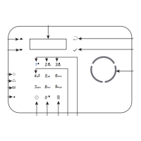
Figure 7
Refer to Page 5 for Alarm Function Adjustments
Before proceeding with Step 4
!!
!!
4