2-14
SPEC
E
MAINTENANCE SPECIFICATIONS
Pulser coil
Output peak voltage lower
limit (W/R – W/G, W/Y – W/Br,
W/B – W/L)
@ cranking 1 V 3.0 2.5
@ cranking 2 V 2.0 2.0
@ 1,500 r/min V 8.0 9.5
@ 3,500 r/min V 14 16
IGNITION CONTROL SYSTEM
Crank position sensor
Output peak voltage lower
limit (G – G)
@ cranking 1 V 3.0
@ cranking 2 V 2.0
@ 1,500 r/min V 5.5
@ 3,500 r/min V 6.0
Engine cooling water
temperature sensor
Resistance (B/Y – B/Y)
@ 5˚C (41˚F) kΩ 128
@ 20˚C (68˚F) kΩ 54 - 69
@ 100˚C (212˚F) kΩ 3.02 - 3.48
Thermo switch (P – B)
OFF → ON ˚C (˚F) 84 - 90 (183 - 194)
ON → OFF ˚C (˚F) 60 - 74 (140 - 165)
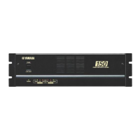
Oil level sensor
(engine oil tank)
Float position a
“OFF”
mm (in) 3 - 6 (0.12 - 0.24)
Float position b
“ON”
mm (in) 33 - 36 (1.30 - 1.42)
Float position c
“ON”
mm (in) 53 - 56 (2.09 - 2.20)
Oil level gauge
(sub-oil tank)
Float position d “ON” mm (in) 150 - 153 (5.91 - 6.02)
STARTING SYSTEM
Fuse 1 V-A 12-30 12-30
Fuse 2 V-A 12-20 —
Fuel enrichment valve
Resistance (L – B) Ω 3.4 - 4.0
* Cranking 1: Open circuit voltage.
Cranking 2: Loaded circuit voltage.
Item Unit
Model
Oil injection
(and 225DET)
Pre-mix
(except for 225DET)