2-2
E
EMU01206
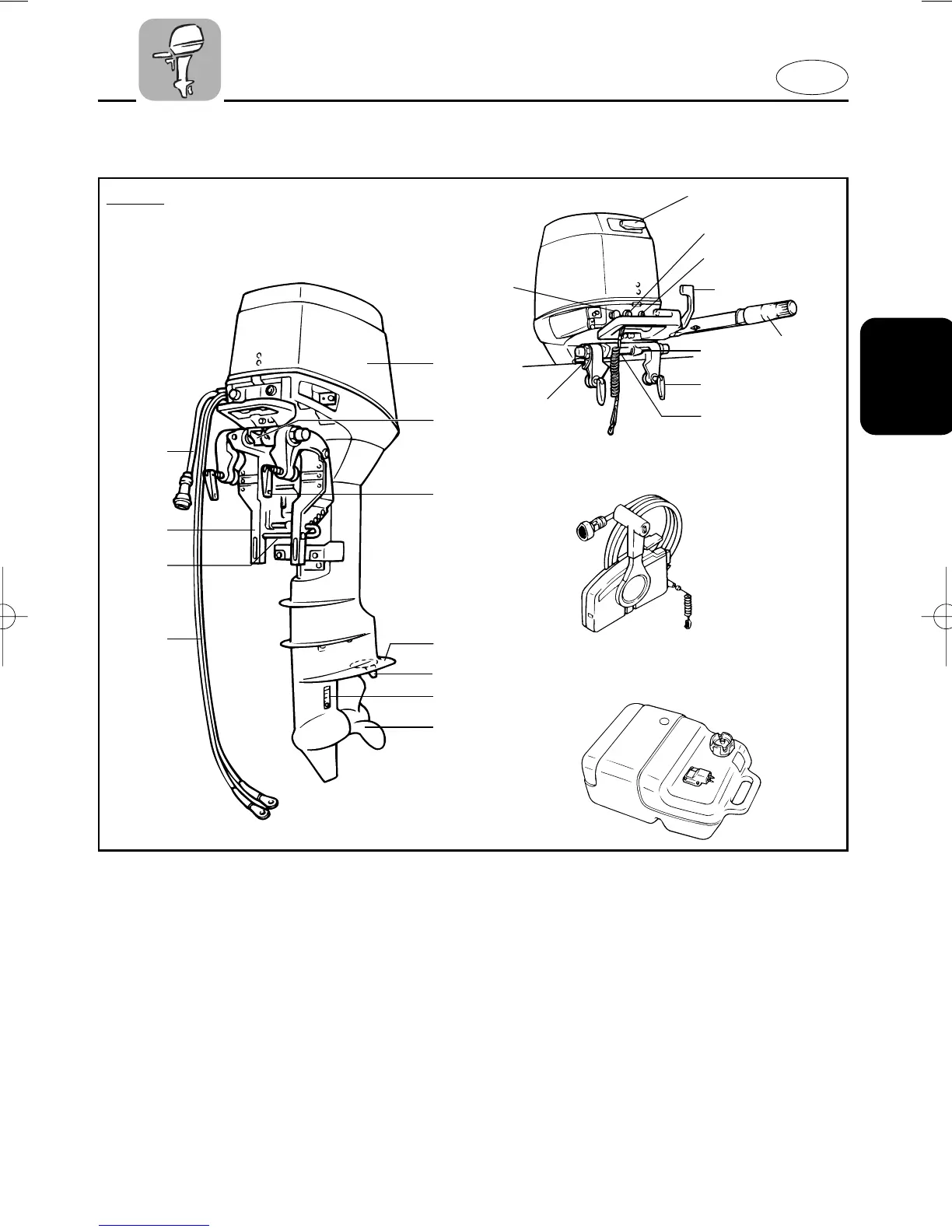
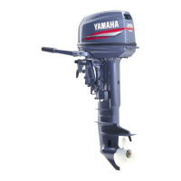
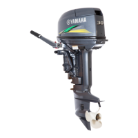
MAIN COMPONENTS
701061
101113**
t
y
u
r
w
e
101111
q
i
!0
o
!2
!8
!4
!5
!6
!7
@0
!3
w
e
!1
!9
@1
1 Top cowling
2 Tilt-lock lever
3 Transom-clamp handle
4 Anti-cavitation plate
5 Trim tab
6 Cooling water inlet
7 Propeller
* 8 Battery lead
9 Trim angle adjusting rod
0 Clamp bracket
q Wiring harness
* w Recoil starter handle
e Engine stop button/Engine stop lanyard
switch
r Warning lamp
* t Gear shift lever
* y Throttle-control grip/tiller handle
* u Shallow water lever
* i Rope attachment
* o Choke knob
* p Remote control box
* a Fuel tank
* May not be exactly as shown; also may not
be included as standard equipment on all
models.
25-3/30
6L2-9-1H 2 4/20/01 1:52 PM Page 3