C
cassandra13Sep 12, 2025
What causes noise inside the disc tray of my Yamaha CDX-596?
- DDr. Jennifer AndersonSep 12, 2025
If you're hearing noise from inside the disc tray of your Yamaha CD Player, the disc might be warped. Try replacing the disc.
What causes noise inside the disc tray of my Yamaha CDX-596?
If you're hearing noise from inside the disc tray of your Yamaha CD Player, the disc might be warped. Try replacing the disc.
Why is there no sound from the headphones on my Yamaha CDX-596 or CDX-496?
If you're not getting any sound from the headphones on your Yamaha CDX-596 or CDX-496, check that the – OUTPUT LEVEL + buttons are not set to the minimum. Adjust the volume using these buttons.
| Type | CD Player |
|---|---|
| Disc formats | CD, CD-R, CD-RW |
| Frequency response | 2 Hz - 20 kHz |
| Dynamic range | 100 dB |
| Total harmonic distortion | 0.0025% |
| Output voltage | 2V |
| Digital outputs | Coaxial, Optical |
| Power Consumption | 15 W |
Specifies critical component requirements and testing procedures for safe servicing.
Provides instructions for eye protection and safe handling of the laser diode during servicing.
Alerts users to lead and other chemicals, with safe handling practices.
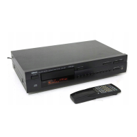
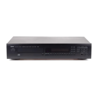
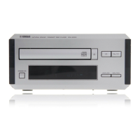
Illustration and labeling of rear panel connectors for the A model.
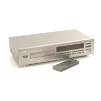
Illustration and labeling of rear panel connectors for G, B models.
Details output level, SNR, frequency response, dimensions, and weight of the unit.
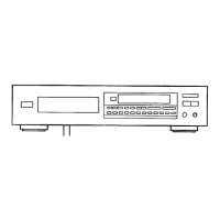
Step-by-step instructions for removing the unit's top cover.
Procedure for detaching and removing the front panel assembly.
Guide for disconnecting and removing the CD mechanism unit.
Steps to detach the tray unit, chucking unit, and stopper pin.
Instructions for removing the drive unit and pick-up head.
Lists panel key operations and functions during test mode activation.
Lists remote control key operations and functions during test mode.
Table detailing error codes, their descriptions, and corresponding states.
Flowcharts to diagnose and resolve error codes like X0, X7, X8, 94, A5.
Diagnosing issues with tray opening, closing, or partial movement.
Troubleshooting steps for no sound or interrupted sound during playback.
Steps to resolve when the unit acts as if no disc is loaded.
Troubleshooting for sound skips and problems with playback search functions.
Pinout details for the display unit and related components.
Mapping of grid patterns to display segments and pin assignments.
Details anode connections for display segments and their corresponding pins.
Pinout and function details for the YSZ914B-F DAFC IC.
Pinout and function details for the MN35511AL signal process controller IC.
Pinout and function details for the uPD78076GF-088 system control IC.
Foil side layout of Main P.C.B. (1) showing component references and positions.
Foil side layout of Main P.C.B. (2) showing component references and positions.
Foil side layout of Main P.C.B. (3) showing component references and positions.
Foil side layout of Main P.C.B. (4) showing component references and positions.
Foil side layout of Main P.C.B. (5) showing component references and positions.
Analysis of EFM waveform at Point A (IC1, Pin 10) showing voltage and time characteristics.
Analysis of waveform at Point B (IC3, Pin 59) showing voltage and time characteristics.
Analysis of waveform at Point C (IC300, Pin 10) showing voltage and time characteristics.
Analysis of waveform at Point D (IC200, CH1/CH2) showing voltage and time characteristics.
Diagram showing pin connection details for transistors, diodes, and ICs in the schematic.
Schematic of the remote transmitter and a table of key functions with custom/data codes.