Do you have a question about the Yamaha CDX-470 and is the answer not in the manual?
Information on critical components and leakage current testing for service personnel.
Instructions for protecting eyes from laser beams and warnings about chemical content.
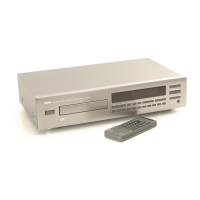
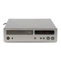
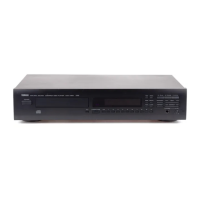
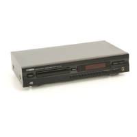
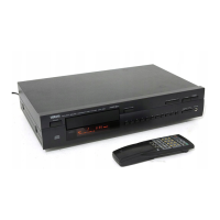
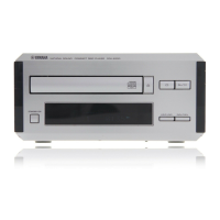
Illustration and identification of front panel controls and indicators for the CDX-470.
Detailed technical specifications for the CDX-470 model.
Physical dimensions and measurements of the CDX-470.
Identifies rear panel input/output connectors and labels for the CDX-470.
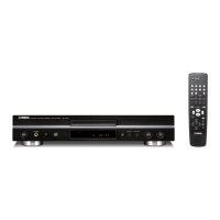
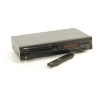
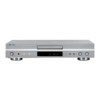
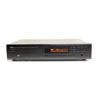
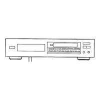
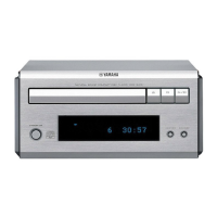
Illustration and identification of front panel controls and indicators for the CDX-570.
Identifies rear panel input/output connectors and labels for the CDX-570.
Detailed technical specifications for the CDX-570 model.
Physical dimensions and measurements of the CDX-570.
Overview of internal components and their locations within the unit.
Step-by-step guide for disassembling the CDX-470 and CDX-570 units.
Identification of test points and potentiometers for calibration procedures.
Steps to enter the service test mode for adjustments and diagnostics.
Procedures for adjusting focus offset and track offset using test points.
Procedures for adjusting EF balance and focus balance using test points and waveforms.
Procedures for adjusting focus and tracking servo gain using oscilloscope measurements.
Steps to confirm track offset, EF balance, and focus offset after adjustments.
Details on using various test modes for diagnostics and confirmation.
List and explanation of error codes displayed during operation or diagnostics.
Foil side layout of the main PCB for CDX-470, showing component locations.
Foil side layout of the main PCB for CDX-570, showing component locations.
Visual representations of expected waveforms at various test points for troubleshooting.
Detailed information on IC pin functions and descriptions for system control.
Detailed circuit diagram for the CDX-470 player.
Detailed circuit diagram for the CDX-570 player.
Comprehensive list of electrical components used in the CDX-470/570.
Cross-reference table for carbon resistor values and part numbers.
List of mechanical components and exploded view for the CDX-470.
List of mechanical components and exploded view for the CDX-570.
Detailed views and parts list for the pickup mechanism unit.
Circuit diagrams for CDX-470 remote controls (U, C, R, A and G, B models).
Circuit diagram for the CDX-570 remote control transmitter.
| Type | CD Player |
|---|---|
| Digital converter | 1-bit DAC |
| Frequency Response | 2 Hz to 20 kHz |
| Dynamic range | 96 dB |
| Total Harmonic Distortion | 0.0025% |
| Output Level | 2V |
| Line output | Yes |
| Digital Output | Optical |
| Disc format | CD |