EasyManua.ls Logo

Yamaha CDX-E200 Service Manual

Yamaha CDX-E200
33 pages
To Next Page IconTo Next Page
Page #1 background imageLoading...
Page #1 background image
CDX-E200
CDX-E200
100745
SERVICE MANUAL
CDX-E200
IMPORTANT NOTICE
This manual has been provided for the use of authorized YAMAHA Retailers and their service personnel.
It has been assumed that basic service procedures inherant to the industry, and more specifically YAMAHA Products, are already
known and understood by the users, and have therefore not been restated.
WARNING: Failure to follow appropriate service and safety procedures when servicing this product may result in personal
injury, destruction of expensive components and failure of the product to perform as specified. For these reasons,
we advise all YAMAHA product owners that all service required should be performed by an authorized
YAMAHA Retailer or the appointed service representative.
IMPORTANT: The presentation or sale of this manual to any individual or firm does not constitute authorization, certification or
recognition of any applicable technical capabilities, or establish a principle-agent relationship of any form.
The data provided is believed to be accurate and applicable to the unit(s) indicated on the cover. The research, engineering, and
service departments of YAMAHA are continually striving to improve YAMAHA products. Modifications are, therefore, inevitable
and specifications are subject to change without notice or obligation to retrofit. Should any discrepancy appear to exist, please contact
the distributor's Service Division.
WARNING: Static discharges can destroy expensive components. Discharge any static electricity your body may have accumu-
lated by grounding yourself to the ground buss in the unit (heavy gauge black wires connect to this buss).
IMPORTANT: Turn the unit OFF during disassembly and parts replacement. Recheck all work before you apply power to the unit.
ERROR MESSAGE...............................................10–11
IC DATA ................................................................12–16
DISPLAY DATA ..........................................................17
BLOCK DIAGRAM................................................18–19
PRINTED CIRCUIT BOARD ................................20–23
IC BLOCK .............................................................24–25
PIN CONNECTION DIAGRAM................................... 25
SCHEMATIC DIAGRAM ............................................. 26
PARTS LIST.......................................................... 27–35
CONTENTS
TO SERVICE PERSONNEL ..................................... 1–2
PREVENTION OF ELECTROSTATIC DISCHARGE TO
ELECTROSTATICALLY SENSITIVE DEVICES ......... 2
REAR PANELS ............................................................. 3
SPECIFICATIONS......................................................... 3
INTERNAL VIEW .......................................................... 4
DISASSEMBLY PROCEDURES ..............................4–5
STANDARD OPERATION CHART .......................... 6–7
TEST MODE..............................................................8–9
CRX-E200 is composed of RX-E200 and
CDX-E200. This is a service manual for
the CDX-E200.
For service manuals of RX-E200, please
refer to the service manuals with the
following publication numbers :
RX-E200 100742
For the system operation, please refer
to Service Manual for the RX-E200.
MINI COMPONENT SYSTEM CRX-E200

Other manuals for Yamaha CDX-E200

Question and Answer IconNeed help?

Do you have a question about the Yamaha CDX-E200 and is the answer not in the manual?

Yamaha CDX-E200 Specifications

General IconGeneral
TypeCD Player
Disc CompatibilityCD, CD-R/RW
Frequency Response2 Hz - 20 kHz
Signal-to-Noise Ratio105 dB
Dynamic Range96 dB
Digital OutputOptical
Weight3.5 kg
Channel separation100 dB
Output Level2.0 V (at 1 kHz, 0 dB)
OutputAnalog Audio (RCA)
Total Harmonic Distortion0.003% (1 kHz)

Summary

Service Personnel Safety Guidelines

Laser Safety Precautions

Essential safety measures to prevent eye and skin damage from laser radiation during servicing.

Laser Emitting Conditions and Protection

Details laser emission times and protective measures, including diode properties.

Electrostatic Discharge (ESD) Prevention

ESD Prevention Techniques and Grounding

Methods to prevent component damage from static electricity and proper grounding procedures.

Rear Panel and Specifications

Rear Panel Layout

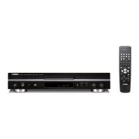
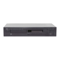
Illustrates the rear panel connections for different models.

Technical Specifications and Dimensions

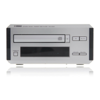
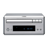
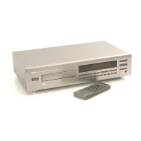
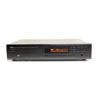
Lists key technical specifications and physical dimensions of the CDX-E200 unit.

Internal Views and Disassembly Procedures

Internal Unit Views

Displays internal component layout and identification.

Top Cover, Front Panel, and CD Mechanism Removal

Instructions for removing the top cover, front panel, and CD mechanism unit.

Tray and Pick-up Head Removal

Steps for removing the CD tray unit and the laser pick-up head.

Standard Operation Chart

Test Mode Operations

Test Mode Key Functions

Details the functions of panel keys and remote controller keys within the test mode.

Test Command Functions

Lists and describes the functions corresponding to specific test command numbers.

Error Message Guide

Error Message Troubleshooting

Lists error messages and provides troubleshooting flowcharts for common issues.

System Malfunction Troubleshooting

Troubleshooting Common System Issues

Guides for resolving various operational problems like tray issues, audio playback, and skipping.

Integrated Circuit Data

IC103 Microprocessor Pinout

Detailed pin assignments and functions for the μPD78076GF-103-3BA microprocessor.

IC102 Signal Processor Pinout

Pin assignments and functional descriptions for the MN35511AL Signal Processor & Controller.

Display Unit Information

Display Data, Pin, and Grid Assignments

Covers display data, pin connections, and grid/anode assignments for the display unit.

System Block Diagram

Printed Circuit Board Layouts

Integrated Circuit Block Diagrams

IC Block Diagrams and Pin Connections

Simplified block diagrams and pin connection details for major ICs.

Schematic Diagram

Parts List - Electrical Components

Electrical Component Details and Abbreviations

Lists electrical parts with details and defines abbreviations used in the list.

Exploded View - Main Assembly

Mechanical Parts List

Exploded View - CD Mechanism Unit

Mechanical Parts List - CD Mechanism

Exploded View - Drive Unit

Carbon Resistor Specifications

Related product manuals