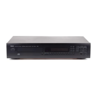
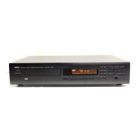
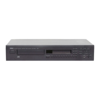
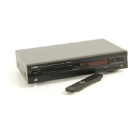
CDX-E200
CDX-E200
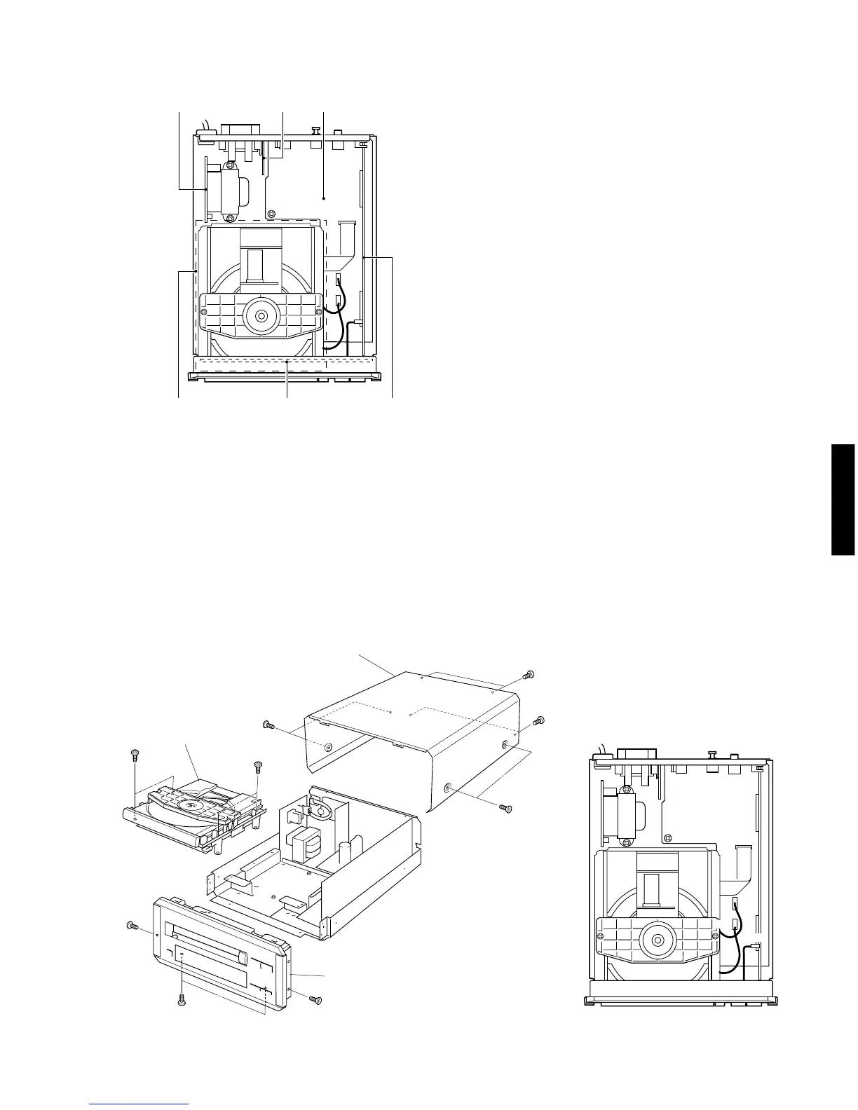
q MAIN (4) P.C.B.
w MAIN (5) P.C.B.
e MAIN (1) P.C.B.
r CD MECHANISM UNIT
t MAIN (3) P.C.B.
y MAIN (2) P.C.B.
■ INTERNAL VIEW
4
■ DISASSEMBLY PROCEDURES (Remove parts in disassembly order as numbered.)
1. Removal of Top Cover
a. Remove 4 screws ( q
) and 4 screws
( w
)
in Fig. 1.
b. Lift the Top Cover at the rear and move it rear-ward slantingly.
2. Removal of Front Panel
a. Remove a connector (CB102) in Fig. 2.
b. Remove 2 ( e ) screws and 2 screws
( r
)
in Fig. 1.
c.
Remove 2 hooks and then pull the Front Panel forward.
3. Removal of CD Mechanism Unit
a. Remove 3 connectors (CB1, CB2, CB3) in Fig. 2.
b. Remove 4 screws ( t ) in Fig. 1.
Fig. 2
Fig. 1
e
e
q
q
w
r
Top Cover
CD Mechanism
Unit
Front Panel
q w e
y
r
t
w
t
t
CB1
CB2
CB3
CB102