Do you have a question about the Yamaha CS-15 and is the answer not in the manual?
Explains terminal naming conventions and wire color coding for circuit board connections.
Defines standard electronic symbols used for transistors, diodes, FETs, and switches.
Lists abbreviations for wire colors and their corresponding Japanese and English names.
Illustrates common logic gate symbols and their truth tables.
Step-by-step guide for removing the synthesizer's main panel.
Instructions on how to safely detach the keyboard assembly.
Guidance on carefully removing internal circuit boards from the unit.
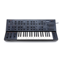
Details the keyboard type, number of keys, and octaves.
Lists the range and function of various synthesizer controls like LFO, VCO, VCF, VCA.
Details the time and level parameters for Envelope Generators 1 and 2.
Specifies output levels and portamento time characteristics.
Describes the pitch bend lever range and control.
Details external connections and control voltage inputs/outputs on the rear panel.
Lists controls and features available on the front panel.
Provides information on power requirements, dimensions, and weight.
Procedures for calibrating the Voltage Controlled Oscillator 1 parameters.
Instructions for verifying waveforms generated by the wave shape converter circuits.
Steps for adjusting the glide circuit and tuning parameters for VCO 1.
Calibration procedures for the VCO detune circuit and Channel II.
Calibration and verification steps for the CPB circuit board.
Procedures for adjusting the Attack, Decay, Sustain, and Release parameters of EG-1.
Calibration and voltage checks for the voltage regulator circuit board.
Procedures for checking and calibrating the SSK circuit board.
Calibration and verification steps for the CPA circuit board.
Pinout and function description for the VCO IC used on the CPA board.
Pinout and function description for the VCA IC used on the CPB board.
| Brand | Yamaha |
|---|---|
| Model | CS-15 |
| Category | Synthesizer |
| Language | English |