EasyManuals Logo

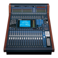
Yamaha DM1000 Service Manual

Yamaha DM1000
307 pages
To Next Page IconTo Next Page
To Previous Page IconTo Previous Page
Page #50 background imageLoading...
Page #50 background image
DM1000/MB1000/SP1000
50
PIN
NO.
I/O FUNCTIONNAME
PIN
NO.
I/O FUNCTIONNAME
1
2
3
4
5
6
7
8
9
10
11
12
13
14
15
16
17
18
19
20
21
22
23
24
D5
D6
D7
/IRQ0
/IRQ1
Vss
/IRQ2
IRQ3
/RD
/WR
/CE
/ASTB
TESTSIO
RX0
TX0
RX1
TX1
Vss
Vdd
RX2
TX2/BO2
RX30
TX30
TX31
I/O
I/O
I/O
I/O
I/O
I/O
I/O
I
I
I
I
I
I
O
I
O
I
O
I
O
I
Data Bus
Interrupt Request Port 0
Interrupt Request Port 1
Ground
Interrupt Request Port 2
Interrupt Request Port 3
Read Signal Input
Write Signal Input
Chip Enable Input
Address Strobe (Not used: to ground)
Input with Pull-down Resistor (50k)
Receive Data 0
Transmit Data 0
Receive Data 1
Transmit Data 1
Ground
Power Supply
Receive Data 2
Transmit Data 2
Receive Data 30
Transmit Data 30
Receive Data 31
25
26
27
28
29
30
31
32
33
34
35
36
37
38
39
40
41
42
43
44
45
46
47
48
TX31
RX32
TX32
RX33
TX33
/IC
Vss
XI
Vss
XO
A0
A1
A2
A3
A4
A5
CPUCLK
Vss
Vdd
D0
D1
D2
D3
D4
O
I
O
I
I/O
I
I
I/O
I
I
I
I
I
I
I
I/O
I/O
I/O
I/O
I/O
Transmit Data 31
Receive Data 32
Transmit Data 32
Receive Data 33
Transmit Data 33
Initial Clear
Ground
Quartz Crystal Input
Ground
Quartz Crystal Onput
Address Bus
CPU Clock
Ground
Power Supply
Data Bus
MBCG46183-129PFV-G (XV833A00) Gate Array (SIO4)
MAIN: IC651
PIN
NO.
I/O FUNCTIONNAME
PIN
NO.
I/O FUNCTIONNAME
1
2
3
4
5
6
7
8
9
10
11
12
13
14
15
16
17
18
19
20
21
22
23
24
25
26
27
28
29
30
31
32
RA1
RB1
RA2
RB2
V
SS
RA3
RB3
RA4
RB4
V
SS
RA5
RB5
RA6
RB6
V
SS
RA7
RB7
RA8
RB8
A0
A1
A2
V
SS
RDN
CSN
V
DD
ASN
A3N
SEL
NC
NC
NC
I
I
I
I
I
I
I
I
I
I
I
I
I
I
I
I
I
I
I
I
I
I
I
I
Encoder input
Ground
Encoder input
Ground
Encoder input
Ground
Encoder input
Address bus
Ground
Read
Chip select
Power supply +5V
Address strobe
Address bus
Bus select
Not used
33
34
35
36
37
38
39
40
41
42
43
44
45
46
47
48
49
50
51
52
53
54
55
56
57
58
59
60
61
62
63
64
D0
D1
V
SS
D2
D3
V
SS
D4
D5
V
SS
D6
D7
V
SS
NC
NC
RA9
RB9
RA10
RB10
RA11
RB11
RA12
RB12
RA13
RB13
RA14
V
DD
RB14
RA15
RB15
RA16
RB16
V
SS
O
O
O
O
O
O
O
O
I
I
I
I
I
I
I
I
I
I
I
I
I
I
I
I
Data bus
Ground
Data bus
Ground
Data bus
Ground
Data bus
Ground
Not used
Encoder input
Power supply +5V
Encoder input
Ground
SGH603064F-62F (XV973A00) Gate Array
FD: IC302, 303

Table of Contents

Other manuals for Yamaha DM1000

Questions and Answers:

Question and Answer IconNeed help?

Do you have a question about the Yamaha DM1000 and is the answer not in the manual?

Yamaha DM1000 Specifications

General IconGeneral
Sampling Frequency44.1kHz, 48kHz, 88.2kHz, 96kHz
TypeDigital Mixing Console
TalkbackYes
MIDI I/OYes
Word ClockYes
Sampling Rate44.1kHz, 48kHz, 88.2kHz, 96kHz
Bit Depth24-bit
DisplayLCD
Buses8
Digital I/OADAT, AES/EBU
Analog Inputs16
Inputs - Mic Preamps16
Inputs - Line16
Outputs - Main8
Outputs - DigitalAES/EBU, ADAT, TDIF
EQ Bands4-band parametric
EffectsInternal Effects Processors
Computer ConnectivityFireWire

Related product manuals