3
RHH135
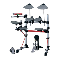
Fig.1
(図 1)
[100]:PWHeadTappingScrew-B(Bタイト+PWH)
3.0X12MFZN2B3(WM788200)
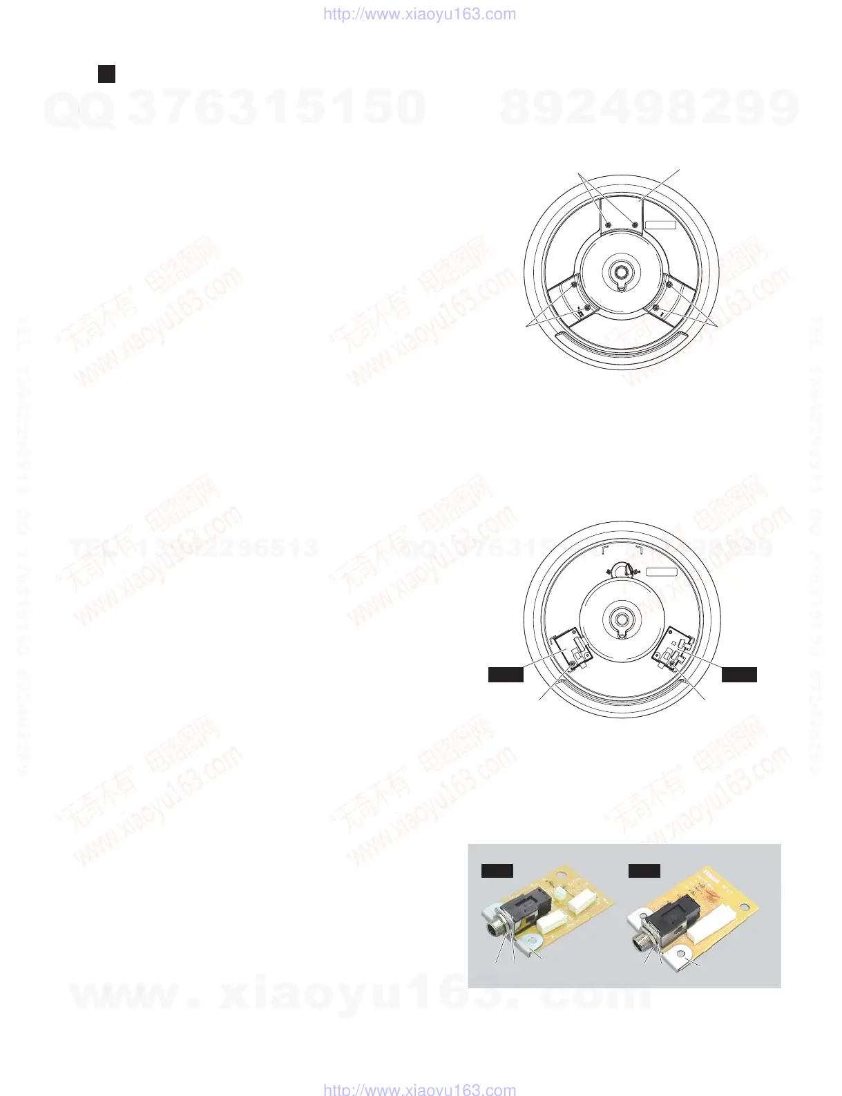
Fig.2
(図 2)
[110]: BindHeadTappingScrew-B(Bタイト+BIND)
3.0X8MFZN2W3(WE774300)
<Bottom view(底から見た図)>
[100]
Rear cover
(リアカバー)
[100] [100]
<Bottom view(底から見た図)>
[110B]
JK2 JK1
[110A]
JK2JK1
[A] [C] [D][B]
Jack holder
(ジャックホルダー)
Jack holder
(ジャックホルダー)
Photo 1
(写真 1)
DISASSEMBLY PROCEDURE(分解手順)
1. JK1 Circuit Board, JK2 Circuit Board
(Time required: About 1 minute)
1-1 Remove the following screws and remove the rear
cover. (Fig. 1)
[100]: 6 pcs.
1. JK1 シート、JK2 シート
(所要時間:約 1 分)
1-1 下記のネジを外してリアカバーを外します。(図 1)
[100]:6 本
1-2 下記のネジを外して JK1 シートを外します。(図 2)
[110A]:1 本
※ ジャックホルダーは JK1 シートの構成部品ではあ
りません。JK1 シートを交換する際は、[A] のナッ
ト 1 個と [C] のワッシャー 1 枚を外してジャック
ホルダーを取り外し、新しい JK1 シートに取り付
けてください。(写真 1)
1-3 下記のネジを外して JK2 シートを外します。(図 2)
[110B]:1 本
※ ジャックホルダーは JK2 シートの構成部品ではあ
りません。JK2 シートを交換する際は、[B] のナッ
ト 1 個と [D] のワッシャー 1 枚を外してジャック
ホルダーを取り外し、新しい JK2 シートに取り付
けてください。(写真 1)
1-2 Remove the following screw and remove the JK1
circuit board. (Fig. 2)
[110A]: 1 pc.
* The jack holder is not part of the JK1 circuit
board. When replacing the JK1 circuit board,
remove the nut marked [A] and washer marked
[C] to remove the jack holder, and install it on
the new JK1 circuit board. (Photo 1)
1-3 Remove the following screw and remove the JK2
circuit board. (Fig. 2)
[110B]: 1 pc.
* The jack holder is not part of the JK2 circuit
board. When replacing the JK2 circuit board,
remove the nut marked [B] and washer marked
[D] to remove the jack holder, and install it on
the new JK2 circuit board. (Photo 1)
w
w
w
.
x
i
a
o
y
u
1
6
3
.
c
o
m
Q
Q
3
7
6
3
1
5
1
5
0
9
9
2
8
9
4
2
9
8
T
E
L
1
3
9
4
2
2
9
6
5
1
3
9
9
2
8
9
4
2
9
8
0
5
1
5
1
3
6
7
3
Q
Q
TEL 13942296513 QQ 376315150 892498299
TEL 13942296513 QQ 376315150 892498299
http://www.xiaoyu163.com
http://www.xiaoyu163.com

 Loading...