EasyManua.ls Logo

Yamaha DVR-S100 User Manual

Yamaha DVR-S100
144 pages
To Next Page IconTo Next Page
Page #1 background imageLoading...
Page #1 background image
100777
P.O.Box 1, Hamamatsu, Japan
CONTENTS
TO SERVICE PERSONNEL .......................................... 2
PREVENTION OF ELECTRO STATIC DISCHARGE ... 4
LOCALE MANAGEMENT INFORMATION ................... 4
SYSTEM COMPOSITION /  ..................... 5
FRONT PANELS ........................................................ 5~6
REMOTE CONTROL PANELS ...................................... 7
REAR PANELS .......................................................... 7~9
SPECIFICATIONS.................................................. 10~11
INTERNAL VIEW ......................................................... 12
DVR-S100 DISASSEMBLY PROCEDURE /
DVR-S100  ............................................... 13~17
SW-S100 DISASSEMBLY PROCEDURE /
SW-S100   18~19
ASSEMBLING AND DISASSEMBLING THE MECHANISM UNIT /
 ............................. 20~29
SERVICE MODE AND SELF-DIAGNOSIS FUNCTION /
  30~37
OPTICAL PICKUP SELF-DIAGNOSIS AND REPLACEMENT PROCEDURE /
  38~39
OPTICAL PICKUP TILT ADJUSTMENT /
..................................... 40~42
ELECTRICAL CONFIRMATION /   42~43
DSP SELF DIAGNOSIS FUNCTION (DIAG)/
DSP自己診断機能(ダイアグ) ............................. 44~61
DISPLAY DATA ..................................................... 62~65
IC DATA ................................................................. 66~73
BLOCK DIAGRAM ................................................. 74~79
PRINTED CIRCUIT BOARD .................................. 80~91
PIN CONNECTION DIAGRAM .................................... 92
SCHEMATIC DIAGRAM ...................................... 93~110
PARTS LIST ....................................................... 111~141
REMOTE CONTROL.................................................. 142
Parts List for Carbon Resistors .............................. 143
SERVICE MANUAL
DVD HOME THEATER SOUND SYSTEM
DVR-S100/NX-SW100
DVR-S100/NX-SW100
IMPORTANT NOTICE
This manual has been provided for the use of authorized YAMAHA Retailers and their service personnel.
It has been assumed that basic service procedures inherent to the industry, and more specifically YAMAHA Products, are already
known and understood by the users, and have therefore not been restated.
WARNING: Failure to follow appropriate service and safety procedures when servicing this product may result in personal
injury, destruction of expensive components, and failure of the product to perform as specified. For these reasons,
we advise all YAMAHA product owners that any service required should be performed by an authorized
YAMAHA Retailer or the appointed service representative.
IMPORTANT:
The presentation or sale of this manual to any individual or firm does not constitute authorization, certification or
recognition of any applicable technical capabilities, or establish a principle-agent relationship of any form.
The data provided is believed to be accurate and applicable to the unit(s) indicated on the cover. The research, engineering, and
service departments of YAMAHA are continually striving to improve YAMAHA products. Modifications are, therefore, inevitable
and specifications are subject to change without notice or obligation to retrofit. Should any discrepancy appear to exist, please
contact the distributor's Service Division.
WARNING:
Static discharges can destroy expensive components. Discharge any static electricity your body may have
accumulated by grounding yourself to the ground buss in the unit (heavy gauge black wires connect to this buss).
IMPORTANT:
Turn the unit OFF during disassembly and part replacement. Recheck all work before you apply power to the unit.
本资料由OKXIA视听皮带资源库www.okxia.cn提供
Question and Answer IconNeed help?

Do you have a question about the Yamaha DVR-S100 and is the answer not in the manual?

Yamaha DVR-S100 Specifications

General IconGeneral
Video Recording FormatMPEG-2
TypeDVD Recorder
Disc FormatsDVD-R, DVD-RW, CD-R, CD-RW
Surround SoundDolby Digital
Video OutputComposite, S-Video, Component
Audio InputRCA x 2
Audio OutputAnalog stereo (RCA), optical digital
Recording FormatsDVD-R, DVD-RW
Audio Recording FormatDolby Digital
Output Resolution480i

Summary

Important Service Manual Notices

Authorized Service Personnel and Safety

Manual is for authorized personnel. Follow safety and service procedures to prevent injury and damage.

Static Discharge Prevention

Static discharges can destroy components. Ground yourself before servicing.

Laser Safety Precautions

Laser Radiation Hazard

Product contains a laser component emitting invisible/visible radiation. Avoid eye exposure.

Safe Servicing Procedures

Keep eyes/skin >30cm from laser pickup. Do not stare at beam. Use controls as specified.

Electrostatic Discharge Prevention

Grounding for ESD Prevention

Ground worktable with conductive material. Ground human body with anti-static wrist strap.

Optical Pickup Handling

Laser diode ends are short-circuited during transport. Do not use testers on laser diode.

DVR-S100 Specifications

Audio Section Specifications

Input sensitivity, output level, frequency response, signal-to-noise ratio for audio.

Video and Tuner Section Specs

Video signal types, tuner frequency ranges, FM/AM sensitivity, and tuning ranges.

NX-SW100 Specifications

Amplifier Section Power Ratings

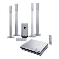
Minimum RMS and maximum output power for front, center, rear, and subwoofer.

Speaker Section and General Specs

Speaker types, drivers, impedance, input power, frequency range, and general specs.

DVR-S100 Disassembly Procedure (Part 1)

Top Cover Unit Removal

Step-by-step instructions for removing the top cover unit from the DVR-S100.

Top Panel Unit Removal

Step-by-step instructions for removing the top panel unit from the DVR-S100.

SW-S100 Disassembly Procedure (Part 1)

Grille Assembly Removal

Steps to remove the front grille assembly, including reassembly notes.

Top Amplifier Unit Removal

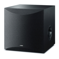
Instructions for removing the top amplifier unit from the SW-S100.

Service Mode Activation

Service Mode Functions

Activate service mode by pressing specific buttons. Functions become DVD/CD.

Self-Diagnosis Error Codes

Self-Diagnosis Function Overview

Unit incorporates self-diagnosis for troubleshooting. Displays errors via UHF display.

Service Mode Diagnosis Codes

In service mode, pressing '0' displays diagnostic codes (F0** to F8**).

Optical Pickup Self-Diagnosis

Optical Pickup Replacement

Replace pickup if laser drive current exceeds threshold. Cause may be static damage.

Optical Pickup Tilt Adjustment Guide

Tilt Adjustment Key Considerations

Essential points before adjustment: ESD measures, component replacement impact, and general notes.

Tilt Adjustment Procedure (Part 1)

Steps to enter service mode, initiate playback, and adjust tangential screw for minimum jitter.

Optical Pickup Tilt Adjustment Procedure (Part 2)

Tilt Adjustment Steps and Optimization

Adjust tilt screws 1 and 2 for minimum jitter, repeat for optimum point and finish with tilt adjustment.

Post-Adjustment Verification

Check for picture/audio degradation after adjustment. Lock screws with screw lock.

DSP Self-Diagnosis Function Overview

DSP Self-Diagnosis Menu Items

Lists DIAG menu items 1-7: DSP THROUGH, RAM THROUGH, PRO LOGIC, SPEAKER SET, etc.

DSP Self-Diagnosis Menu Items (Continued)

Starting DIAG

Press specific keys simultaneously with STANDBY/ON to activate DIAG mode.

AD DATA CHECK/FAN TEST Mode Details

A/D Conversion Value Display

Displays A/D conversion values of panel keys and protection functions in % (5V=100%).

K0/K1 Key Input Function

When K0/K1 menu selected, keys become non-operable. Advance to next sub-menu using ' ' key.

Display Data: PIN Connection

Display Data: Grid Assignment

Diagram and table showing grid assignments for various functions (PGM, TITLE, TRACK, etc.).

Block Diagram: DVD Module (U, C, J models)

Block Diagram: DSP P.C.B.

DVR-S100 PCB Layout: DVD Module (U, C, J)

Pin Connection Diagram: ICs

Pin Connection Diagram: Diodes and Transistors

Diagrams illustrating pin configurations for diodes and transistors.

Schematic Diagram: Main PWB (1/2)

Electrical Parts List - Abbreviations

Electrical Parts List - Capacitors and Connectors

List of capacitors (chip, electrolytic, film, etc.) and connectors with their part numbers.

Parts List: DVR-S100 P.C.B. DSP Components

DVR-S100 Exploded View

DVR-S100 Mechanical Parts List (Part 1)

DVR-S100 Mechanical Parts List (Part 2)

List of mechanical parts for DVR-S100, including supports, dampers, emblems, and screws.

DVD-Mechanism Exploded View

DVD-Mechanism Parts List

List of DVD mechanism parts, including motors, chassis, gears, shafts, and PCB assemblies.

NX-SW100 Mechanical Parts List

Remote Control Layout and Functions

Parts List: Carbon Resistors (1/4W & 1/6W)

Related product manuals