Do you have a question about the Yamaha DXR Series and is the answer not in the manual?
| Series | DXR |
|---|---|
| Type | Powered Speaker |
| Amplifier Class | D |
| Power Output | 1100W (DXR15), 1100W (DXR12), 800W (DXR10), 800W (DXR8) |
| Inputs | XLR |
| Outputs | XLR |
| Mounting Options | Pole mount |
| Woofer | 10", 12", or 15" Cone (Depending on Model) |
| Tweeter | 1.75" |
| DSP Presets | Monitor |
| Protection | Thermal |
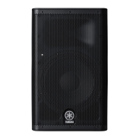
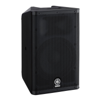
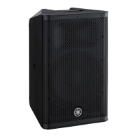
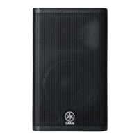
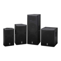
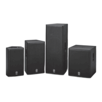
Information and specifications for the DXR Series powered speakers.
Details and parts for U-bracket mounting accessories for DXR Series.
Detailed specifications of the amplifier section, including power, cooling, and DSP.
Identification and layout of controls and connectors on the rear panel.
Step-by-step instructions for disassembling the DXR8 and DXR10 speaker assembly.
Japanese instructions for disassembling DXR8/DXR10 speakers.
Procedure for removing the baffle assembly from DXR8 and DXR10.
Procedure for removing the tweeter speaker from the assembly.
Procedure for removing the amplifier assembly.
Procedure for removing the metal grille assembly for DXR12/DXR15.
Japanese instructions for disassembling DXR12/DXR15 speakers.
Procedure for removing the baffle assembly for DXR12 and DXR15.
Japanese instructions for baffle assembly disassembly for DXR12/DXR15.
Procedure for removing the tweeter speaker for DXR12/DXR15.
Procedure for removing the amplifier assembly for DXR12/DXR15.
Procedure for removing the amplifier cover assembly.
Procedure for removing the TWAMP assembly.
Procedure for removing the AMPS circuit board.
Procedure for removing the SUB1 circuit board.
Continued procedure for removing SUB1 circuit board, including knob and inlet.
Procedure for removing DSP and SUB2 circuit boards.
Required items and software for performing the test program.
Diagram showing how to connect test equipment to the unit.
Overview of the service inspection process and activation.
Steps to activate the diagnostic mode and start the inspection.
Details on the various inspection items covered in the test program.
How to check firmware version and model ID using the diagnostic application.
Procedure for inspecting DSP communication and operational status.
How to inspect the AD input port for temperature sensor voltage readings.
How to inspect analog mute performance on the SP OUT side.
How to inspect analog mute performance on the LINK OUT side.
How to inspect the status of various switches (LED Disable, D-CONTOUR, HPF).
How to inspect the operation of all LEDs (limit, signal, protection, power, etc.).
How to inspect the FAN's condition and speed changes.
How to inspect power supply shutdown when POFF-REQ is activated.
Conditions and equipment required for performing measurements.
Recommended measuring devices and jigs for accurate testing.
Diagram showing the connection of test equipment for inspections.
List of inspection items to be performed on the AMP assembly.
Procedure for measuring power consumption when idling.
Instructions for adjusting the ±VB voltage on the AMPS circuit board.
Procedure for adjusting the VB voltage frequency using VR102.
Confirming power consumption when the unit is idling without signal.
How to confirm the firmware version via diagnostic mode.
How to confirm the model ID displayed by the diagnostic application.
Testing the DC protection circuit's operation by applying voltage.
Measuring output levels at maximum gain settings for various inputs.
Measuring frequency response at 20Hz, 20kHz, and by reference levels.
Measuring total harmonic distortion (THD+N) for different inputs and outputs.
Measuring maximum output levels at 100Hz and 5kHz with THD+N.
Verifying output levels without power supply shutdown, specifically for SP OUT (LF).
Measuring output noise levels with and without MIC/LINE input.
Measuring residual noise levels in the output terminals.
Inspecting analog mute operation and output levels.
Step-by-step instructions for performing the firmware update.
List of electrical components for the AMPS circuit board.
Continuation of the list of electrical components for the AMPS circuit board.
List of electrical components for AMPS and DSP sections.
List of electrical components for the DSP circuit board.
Continuation of the list of electrical components for the DSP circuit board.
List of electrical components for SUB and TWAMP circuit boards.
Continuation of electrical components for SUB and TWAMP circuit boards.
List of electrical components for the TWAMP circuit board.
Overall block diagram showing the functional connections between major modules.
Diagram illustrating signal levels throughout the audio path.
Circuit diagram for the AMPS module, covering power supply and regulators.
Circuit diagram for the AMPS module, detailing signal processing and audio path.
Circuit diagram for the AMPS module, showing transistor and component details.
Circuit diagram for the AMPS module, illustrating DC detection and connections.
Circuit diagram for the DSP module, showing major ICs and power supply.
Detailed circuit diagram for the DSP module, showing operational amplifiers and signal paths.
Circuit diagram for the SUB1 module, showing AC input and power supply.
Circuit diagrams for LED, SUB2, SUB3, and SUB4 modules.
Circuit diagram for the TWAMP module, showing power supply and control circuits.