Do you have a question about the Yamaha DXS Series and is the answer not in the manual?
| Type | Powered Subwoofer |
|---|---|
| Series | DXS |
| Amplifier Class | Class D |
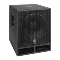
| Woofer Size | 18 inches |
| Inputs | XLR |
| Outputs | XLR |
| Crossover Frequency | 80Hz - 120Hz |
| Phase Switch | 0 or 180 degrees |
| Enclosure Material | Plywood |
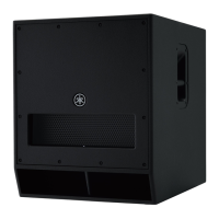
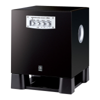
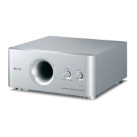
Specific description of the rear panel components and controls.
Steps to remove the metal grille assembly.
Steps to remove the LED panel and circuit board.
Steps to remove the port board assembly.
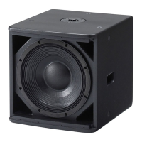
Steps to remove the speaker (woofer) component.
Steps to remove the amplifier assembly.
Steps to remove the amplifier's cover.
Steps to remove the SUBW3 circuit board.
Steps to remove the shield assembly.
Steps to remove the AMPSW circuit board.
Steps to remove the SUBW4 circuit board.
Steps to remove the SUBW1 circuit board.
Steps to remove DSPW and SUBW2 boards.
Steps to remove the DC fan.
Setup steps including items, software, and connections.
Steps for performing the service inspection.
How to activate diagnostic mode and application.
List of specific tests to perform.
Conditions, instruments, jigs, filters, and connections for measurements.
Verifying power, gain, response, distortion, noise, and output.
Checking indicators, switches, fans, mute, protection, and AC operation.
Tools needed for firmware update.
Steps to prepare for firmware update.
How to connect for firmware update.
Steps to perform the firmware update.
Troubleshooting common update errors.
Parts list for the overall unit assembly.
Parts list for the LED panel assembly.
Parts list for the metal grille assembly.
Parts list for the amp assembly.
List of included jigs and accessories.
List of electrical components for AMPSW board.
List of electrical components for DSPW board.
List of electrical components for SUBW boards.
Explains symbols and conventions used in diagrams.
How to locate connectors between sheets.
How connectors are wired between boards.