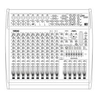
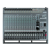
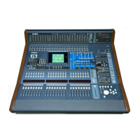
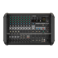
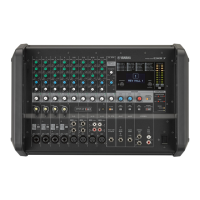
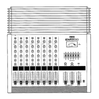
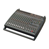
EMX2000
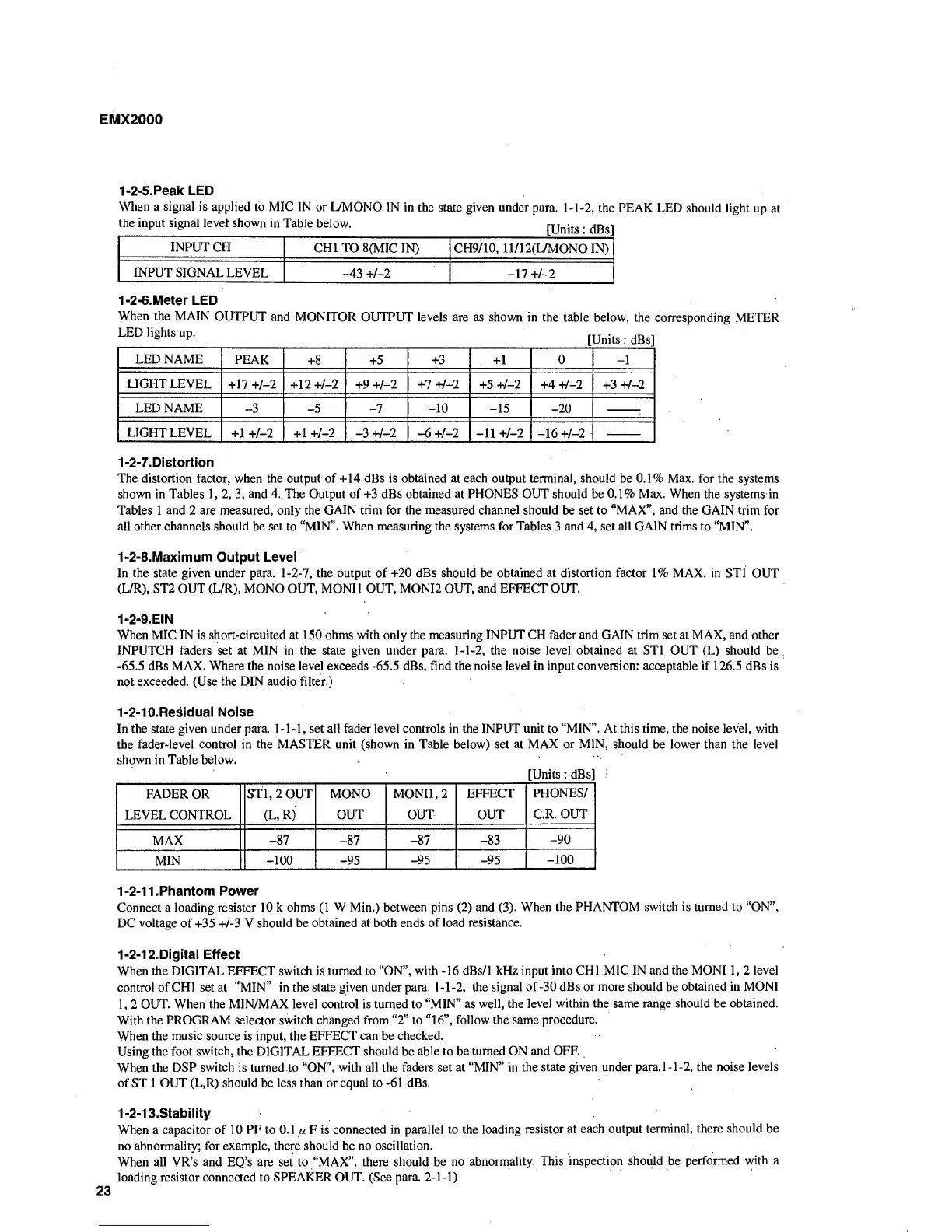
1-2-5.Peak LED
When
a
signal is applied
to MIC IN or L/MONO
IN in the
state
given under
para.
1
-
1
-2,
the PEAK LED should
light up
at
the input signal level shown in
Table below.
[Units
:
dBs^
INPUT CH
CHI TO
8(MIC IN) CH9/10, ll/12(L/MONOIN)
INPUT
SIGNAL LEVEL -43
+/-2 -17 +/-2
1-2-6.Meter LED
When the MAIN
OUTPUT
and MONITOR OUTPUT levels
are as shown in the table below,
the corresponding
METER
[Units :dBs
LED NAME
PEAK
+8 +5
+3 +1
0
-1
LIGHT LEVEL
+17 +
1-1
+12 +
1-1
+9 +
1-1
+7 +
1-1
+5 +
1-1
+4 +
1-1
+3 +
1-1
LED
NAME
-3 -5 -1
-10 -15
-20
LIGHT
LEVEL +1
+
1-1
+1
+
1-1 -3
+
1-1 -6
+
1-1
-11
+
1-1
-16
+
1-1
1-2-7.
Distortion
The distortion factor, when the output of +14 dBs is obtained at each output terminal, should be 0.1% Max. for the
systems
shown in Tables
1, 2, 3,
and 4. The Output of +3 dBs obtained at PHONES OUT should be 0.1% Max. When the
systems in
Tables 1 and 2 are measured, only the
GAIN trim for
the
measured channel
should be set to
“MAX”, and
the GAIN trim for
all other channels should be set to
“MIN”. When measuring
the systems
for Tables
3
and
4,
set
all GAIN trims
to “MIN”.
1-2-8.Maximum Output Level
In the state given under para.
1-2-7,
the output of +20
dBs
should be obtained at distortion factor 1% MAX. in STl
OUT
(L/R), ST2 OUT (L/R), MONO OUT, MONI
1
OUT, MONI2 OUT, and EFFECT OUT.
1-2-9.EIN
When MIC IN is short-circuited
at
150 ohms with only the measuring INPUT CH fader and GAIN trim set at MAX, and
other
INPUTCH
faders
set at
MIN in the
state
given under para.
1-1-2,
the noise level obtained at STl OUT (L) should
be,
-65.5
dBs
MAX. Where the noise level
exceeds
-65.5
dBs, find the noise level in input conversion: acceptable if 126.5
dBs is
not exceeded. (Use the DIN audio filter.)
1-2-10.Residual Noise
In the state given under
para. 1-1-1,
set all fader level controls in the INPUT
unit
to
“MIN”. At this time,
the noise
level,
with
the
fader-level control in the MASTER unit (shown in Table below) set at
MAX or MIN, should
be lower than the level
shown in Table below.
[Units :
dBs^
FADER OR
STl, 2 OUT MONO MONIl,2
LEVEL
CONTROL (L, R)
OUT OUT
MAX
-87
-87
-87 -83
-90
MIN
-100 -95
-95 -95
-100
1
-2-1
1 .Phantom
Power
Connect a
loading resister 10 k ohms
(1
W Min.)
between pins
(2)
and
(3).
When
the PHANTOM switch is turned to “ON”,
DC
voltage
of +35
+/-3
V
should be obtained at both ends
of load resistance.
1-2-12.Digital Effect
When the DIGITAL EFFECT switch is
turned
to “ON”,
with
-16
dBs/1 kHz input
into CHI MIC IN and the MONI
1,
2 level
control
ofCHl setat
“MIN”
in the state given under para.
1-1-2, the signal of
-30dBs or more should
be
obtained in MONI
1,2
OUT. When the MIN/MAX level
control
is turned to
“MIN”
as
well, the
level within the same range should be obtained.
With the PROGRAM selector switch changed from
“2”
to
“16”,
follow the same
procedure.
When the
music source is
input, the
EFFECT can be checked.
Using the foot
switch, the
DIGITAL
EFFECT should
be
able to be turned ON
and OFF.
When the
DSP switch is turned
to “ON”,
with all the faders set at “MIN” in
the state given under
para.
1-1
-2,
the noise levels
of ST 1
OUT (L,R) should be less than or equal to
-61
dBs.
1-2-13.Stability
When a capacitor of 10
PF to
0.1
//
F
is connected in parallel to the
loading
resistor at each output
terminal, there
should
be
no abnormality;
for example, there should be no
oscillation.
When all VR’s and EQ’s are
set
to “MAX”, there
should be no
abnormality. This
inspection should be
performed
with
a
loading resistor connected to
SPEAKER OUT. (See para.
2-1-1)


 To Next Page
 Loading...