EasyManua.ls Logo

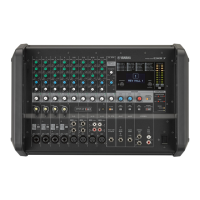
Yamaha EMX 2000 - Power Amplifier Part

Yamaha EMX 2000
69 pages
Print Icon
To Next Page IconTo Next Page
To Previous Page IconTo Previous Page
Loading...
EMX2000
2.
Power
Amplifier Part
2-1.
Setting
Conditions
Setting
conditions are as
follows
unless otherwise
specified.
ST SUB IN 1
L/MONO
STL-STR
Maximum
SPEAKER
L(l), SPEAKER
R(l)
4 ohms (200W
or higher, connect
the resistor
when
inspecting the
power amplifier
section)
CHl-10 fader
•
level
control :
Minimum
SUB IN 2 fader
•
level
control
:
Minimum
TAPE IN fader
•
level
control :
Minimum
Note;
Other control
settings are the
same as mixer part
section
1-1-2.
2-2.
Power
Amplifier
inspections
2-2-1.
Power ON
Muting
The muting relay
should
turn on
2.5
+/-1
seconds
after the
power
switch is turned on.
2-2-2.
Output Terminal
DC
Voltage
When input
terminal is
grounded,
the Output
Terminal DC
Voltage
should be 0
+/-100
mV.
2-2-3.
Gain
When the POWER
AMP switch is
changed
with,
-7.2 dBs signal input into
the input
terminal, the
output shown in
Table
below
should be
obtained.
[Units : dBs]
POWER AMP
Switch
STL-STR
MONO-MONI
SPEAKER
L
(1,
2)
+20.0
+/-2.0
+23.0
+/-2.0
SPEAKER R
(1,
2)
+20.0
+/-2.0
+23.0
+/-2.0
2-2-4.
Frequency
Response
Apply a
signal
to
the input;
the output
level should be
between
-3
and +1
dB at 20 Hz
and 20 kHz, when
1 kHz is set as the
reference.(0
dB)
2-2-5.
Harmonic
Distortion
Apply a
1 kHz
signal
to
the input'; the
output
level should be
200
W + 200 W/4
ohms
(31.2
dBs/ch);
the
distortion ratio
should be
less than 0.5 %.
Apply a
signal of 20
Hz, 1 kHz and 20
kHz to
the input
separately; the
output level
should be 100 W +100 W/4
ohms
(28.2
dBs/ch);
the
distortion ratio should be
less than
0.5 %.
2-2-6.
Residual
Noise
Set
the
POWER
AMP L/BRIDGE and
POWER
AMP level
control at
minimum; the residual
noise should be
le:ss than
-62
dBs.
Notes:
1. Apply
DIN-
AUDIO filter.
2.
When
measuring the
residual noise, be sure
that
inductive noise
does not interfere.
2-2-7.
Stability
Apply a 10
kHz
-3.2
dBs
rectangular signal to
the output and
connect a
4 ohms
resistor and a
capacitor
(10
pF to
0.47
fj.
F)
parallel
to the load
resistor; or connect an
inductor
(10y«
H to 0.47
H) serial to
the load
resistor. Confirm that
the output signal
should be illustrated
below.
Overshoot; Vp/Vo
is less than or
equal to 1.8
Ringing:
5
waves
and less than 5
waves
2-1
-1
.
Control Panel
Setting
Input
Terminal
:
Power AMP switch
:
Power AMP
(L/BRIDGE,
R) level
control
:
Measuring Output
Terminal
:
Output Load
:
24