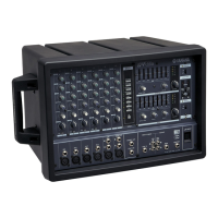
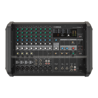
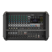
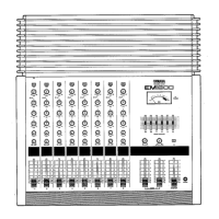
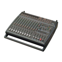
EMX2000
2-2-8.
Protection
Apply a
10
Hz signal
to
the input; increase
the input signal so that
the output
signal
is
clipped. Confirm that the protection
does
not operate and the speaker relay should
not activate.
When
applying a 1 Hz, 10 Vp-p
(13.2 dBs) sine wave
signal to the input; confirm
that
the protection operates within
2
seconds and the speaker relay is
turned off. When turning
off the input signal,
confirm that
the
protection stops the operation
within 5 seconds and the
speaker relay is turned on.
2-2-9.
PC Limiter and
Limiter
Apply a 1 kHz 0 dBs sine
wave signal
to
the input and
connect
a
1 ohm (+/-5
% 100 W)
resistor;
confirm that
the
output
signal Vp-p is less than or
equal to 20
V
and the
signal is not rectangular.
2-2-10.
LIMITER
Indicator
When applying
a
+8
dBs sine wave signal to the
input, the LIMITER indicator
should
light on.
2-
2-1
1 . Efficiency
When applying
a +5.2 dBs sine wave signal to
the input,
confirm that
the
power
consumption is
190+/-50W.
3. Main
Bridge
3-
1
.
Setting Conditions
Setting conditions
are as follows
unless otherwise specified.
3-1-1.
Control Panel Setting
Input Terminal
:
Power AMP
switch
:
Power AMP (L/BRIDGE,
R) level control
:
Measuring
Output
Terminal
:
Output Load
:
CHl-10 fader
•
level control
:
SUB IN 2 fader
•
level
control
:
TAPE IN fader
•
level control
:
Note: Other
control settings
are the same as mixer part section
ST
SUB
IN 1
L/MONO
MONO BRIDGE
Maximum
BRIDGE
8 ohms (400W or
higher,
connect the resistor when
inspecting the power amplifier section.)
Minimum
Minimum
Minimum
1
-
1
-
2
.
3-1-2.
Connection
Measuring
instruments input
Measuring instruments
ground
3-2.
MAIN BRIDGE
Inspection
3-2-1
.
Gain
Apply a
-10.2
dBs signal; confirm
that the output level
are
+20.0 dBs+/-2
dB.
3-2-2.
Frequency Response
Apply
a
signal
to
the input;
the output
level should be between
—3
and +1 dB at 20 Hz and 20 kHz
when 1 kHz is set as the
reference.(0 dB)
4. Power Supply Fluctuation
There should
be no operational problems when
the power supply fluctuation is within
±
10
%
of nominal
voltage.
25



 To Next Page