EasyManuals Logo

Yamaha F6BMH User Manual

Yamaha F6BMH
510 pages
To Next Page IconTo Next Page
To Previous Page IconTo Previous Page
Page #270 background imageLoading...
Page #270 background image
CAMSHAFT AND VALVES
REMOVING THE VALVE
Remove:

Valve spring lock 1

Valve spring retainer 2

Valve spring 3

Valve spring seat 4

Intake valve or exhaust valve 5
NOTE:

Set the attachment on to the center of the
spring retainer.

Do not overtighten the valve spring
compressor.
CHECKING THE VALVE AND VALVE
GUIDE
1. Measure:

Valve guide inside diameter
a
Out of specification
ī˜‚
Replace.
2. Measure:

Valve seat width
b
Out of specification
ī˜‚
Replace.
3. Measure:

Valve margin thickness
c
Out of specification
ī˜‚
Replace.
Valve spring compressor:
YM-01253/90890-04019
Attachment:
YM-04018/90890-04018
Valve guide inside diameter
a
(intake guide and exhaust guide):
5.500 - 5.512 mm
( 0.2165 - 0.2170 in)
Valve seat width
b
(intake valve and exhaust valve):
0.6 - 0.8 mm (0.023 - 0.031 in)
Valve margin thickness
c
(intake valve and exhaust valve):
0.7 mm (0.027 in)
5-45

Table of Contents

Questions and Answers:

Question and Answer IconNeed help?

Do you have a question about the Yamaha F6BMH and is the answer not in the manual?
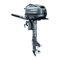
Yamaha F6BMH Specifications

General IconGeneral
Max Output6 hp
Starting SystemManual
Gear Ratio2.08:1
Fuel Induction SystemCarburetor
Ignition SystemCDI
LubricationWet Sump
Oil InjectionNo
Engine Type4-Stroke, SOHC
Weight27 kg
Prop Shaft Horsepower6 hp
Full Throttle RPM Range5, 000 - 6, 000 rpm
Shaft Length15 in
SteeringTiller
Full Throttle Operating Range5, 000 - 6, 000 rpm

Related product manuals