3
Adjustment
3-2
2.
Adjusting the timing belt tension (B10/B14/B14H)
The B10, B14 and B14H series robots use a timing belt to move the table slider.
If the tension of the timing belt is weak, follow the steps below to adjust the belt tension.
w
WARNING
CONTROLLER POWER. IF THE ROBOT OPERATES DURING WORK, THIS MAY CAUSE SERIOUS ACCIDENT.
REQUIRED QUALIFICATIONS DESCRIBED IN “2. QUALIFICATION OF OPERATORS/WORKERS” IN SECTION 4.1 OF
“SAFETY INSTRUCTIONS”.
BE CAREFUL NOT TO NEGLECT TIGHTENING SCREWS OR BOLTS. IF ANY COVER IS NOT SECURED FIRMLY, THIS MAY
CAUSE NOISE, COVER DROPPING AND FLYING, HAND ENTANGLEMENT IN DRIVE UNIT DURING TEACHING, OR BURN
DUE TO HAND IN CONTACT WITH HOT SURFACE. SO, BE SURE TO TIGHTEN ALL THE SCREWS AND BOLTS SECURELY.
w
WARNING
THE MOTOR AND SPEED REDUCTION GEAR CASING ARE EXTREMELY HOT AFTER AUTOMATIC OPERATION, SO BURNS
MAY OCCUR IF THESE ARE TOUCHED. BEFORE TOUCHING THESE PARTS, TURN OFF THE CONTROLLER, WAIT FOR A
WHILE AND CHECK THAT THE PARTS HAVE COOLED.
INJURY CAN OCCUR IF HANDS OR FINGERS ARE SQUEEZED BETWEEN THE DRIVE PULLEY AND BELT. ALWAYS TURN OFF
THE CONTROLLER AND USE CAUTION WHEN HANDLING THESE PARTS.
c
CAUTION
performed again and the point data must be re-specified.
may cause rust.
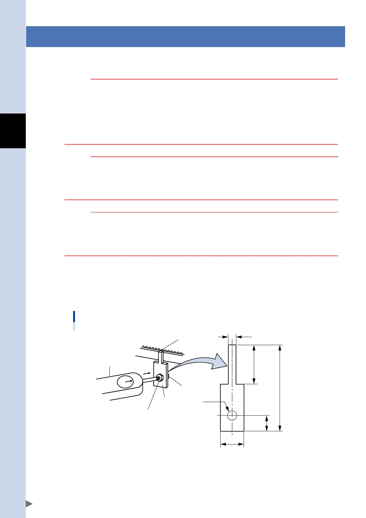
Prepare tools necessary for the adjustment work
•Belttensionadjustmentbolt(accessory)
•Push-pullscale
•Stay(TheusermustmanufacturethisstaywhilereferringtotheFig.below.)
•Tensionmeter
Stay (example)
5
Metal plate of 3.2mm thick
25
55
10
Hole
15
Belt
Push-pull scale
Nut
Nut
Stay
53303-AC-00
FLIP-X_maint_E_V1.50.indb 2 18/05/15 15:01

 Loading...