4
Replacement
4-20
4.
Replacing the drive and speed reduction belts (B10/B14/B14H)
4.1 Replacing the drive belt
w
WARNING
TURN OFF THE CONTROLLER POWER. IF THE ROBOT OPERATES DURING THE REPLACEMENT WORK, THIS MAY CAUSE
SERIOUS ACCIDENT.
REQUIRED QUALIFICATIONS DESCRIBED IN “2. QUALIFICATION OF OPERATORS/WORKERS” IN SECTION 4.1 OF
“SAFETY INSTRUCTIONS”.
BE CAREFUL NOT TO NEGLECT TIGHTENING SCREWS OR BOLTS. IF ANY COVER IS NOT SECURED FIRMLY, THIS MAY
CAUSE NOISE, COVER DROPPING AND FLYING, HAND ENTANGLEMENT IN DRIVE UNIT DURING TEACHING, OR BURN
DUE TO HAND IN CONTACT WITH HOT SURFACE. SO, BE SURE TO TIGHTEN ALL THE SCREWS AND BOLTS SECURELY.
c
CAUTION
data must be re-specified. When removing the parts, check and mark the part positions versus each other so
you can correctly reassemble the parts later.
may cause rust.
1
Turn off the controller power.
2
Place a sign indicating the robot is
being adjusted.
Place a sign indicating the robot is being
adjusted, to keep others from operating the
controller or operation panel.
3
Enter the safety enclosure.
4
Remove the end cover.
Remove the end cover from the non-motor
end.
5
Remove the upper cover.
For models with a long stroke, pull out the
cover parallel with the axis movement
direction.
6
Remove the motor.
Remove the motor while referring to "2.3
B10/B14/B14H" of "2. Replacing the motor" in
this Chapter. (It is unnecessary to remove
the motor if installed horizontally or
downwards.)
7
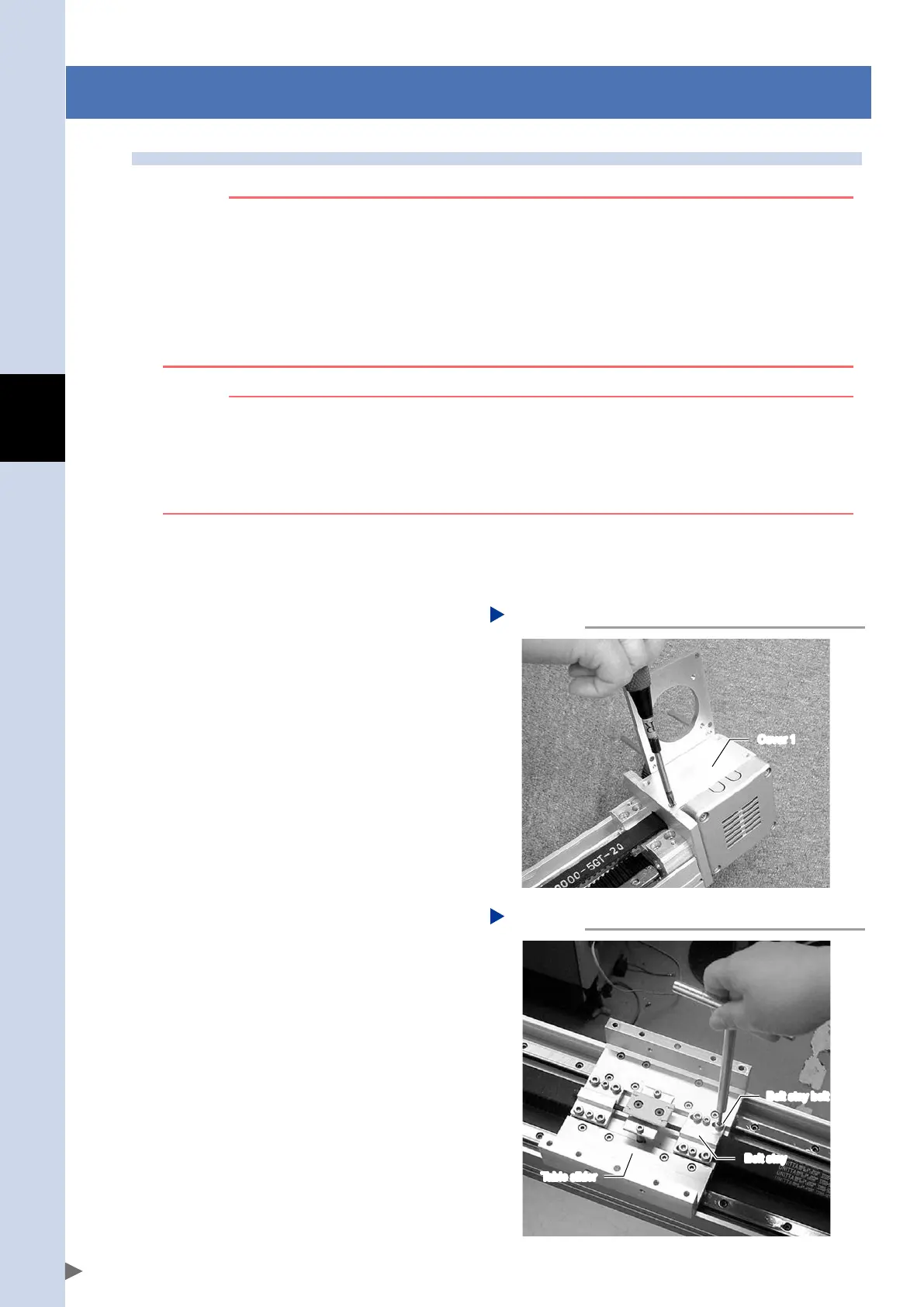
Remove the cover 1.
Removing the cover 1
Step 7
Cover 1
53404-AC-00
8
Remove the belt stay.
Remove the belt stay bolts (4 x 2) and
remove the belt stay from the slider table.
Removing the belt stay
Step 8
Belt stay bolt
Belt stay
Table slider
53405-AC-00
FLIP-X_maint_E_V1.50.indb 20 18/05/15 15:01

 Loading...