Do you have a question about the Yamaha K-200 and is the answer not in the manual?
| Track System | 4-track, 2-channel stereo |
|---|---|
| Tape Speed | 4.76 cm/s |
| Heads | 1 x record/playback, 1 x erase |
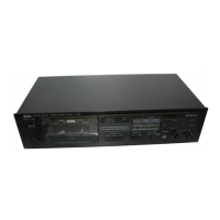
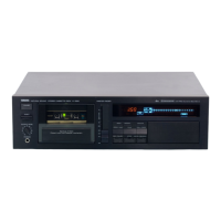
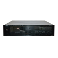
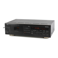
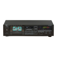
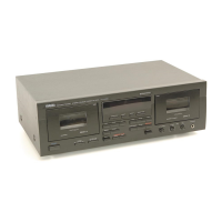
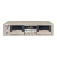
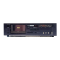
| Type | Cassette Deck |
| Inputs | 1 x line |
| Outputs | Line Out (RCA), Headphone (6.3mm) |
| Signal to Noise Ratio (Dolby B) | 66dB (dolby B) |
| Signal-to-Noise Ratio (Dolby B On) | 66dB (dolby B) |
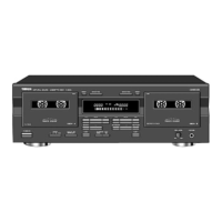
Identifies key controls and indicators on the front panel of the cassette deck.
Connects audio sources for recording and outputs for playback.
Details the power cord connection for mains supply.
Identifies numbered parts such as transformers, motors, and circuit boards from the top.
Steps for removing the top and bottom covers of the unit.
Procedures for detaching the front panel and transport mechanism.
Instructions for removing VU meters and circuit boards.
Calibrating tape speed and setting playback signal levels.
Aligning the R/P head for optimal audio output.
Verifying frequency response accuracy during playback.
Adjusting VU meters and recording input levels.
Verifying bias current for optimal recording quality.
Optimizing recording performance for CrO2, LH, and Metal tapes.
Diagram showing locations of adjustment potentiometers.
Details on tape speed, frequency response, SNR, input/output levels.
Unit size, weight, power supply details, and model variations.
Illustrates the flow of audio signals through the unit's circuitry.
Flowchart detailing logic for FWD and REC button operations.
Flowchart detailing logic for FF, REW, and FF/REW modes.
Detailed electronic schematic of the main circuit board.
Lists common transistors, ICs, diodes, and other component types.
Schematics for record amp, EQ, and Dolby processing circuits.
Diagrams for power supply and control logic circuits.
Diagrams showing copper trace patterns on the main circuit boards.
Diagrams showing component placement and wiring on PCBs.
Information on how the parts list is structured.
Key for country codes used in market designations.
Visual representation of all major parts and their assembly.
List of all parts with numbers, descriptions, and remarks.
Data on part variations based on market and model.
Exploded view diagram of the tape transport mechanism.
List of parts specific to the tape transport mechanism.
Detailed list of capacitors used on the circuit boards.
Further details on capacitors and resistors for circuit boards.
List of resistors with part numbers and resistance values.
List of semiconductor components used on the circuit boards.
List of switches and potentiometers for control and adjustment.
List of fuses, audio jacks, and connection terminals.
List of component holders, solenoids, and system accessories.