8
DX200
■ DISASSEMBLY PROCEDURE
1.
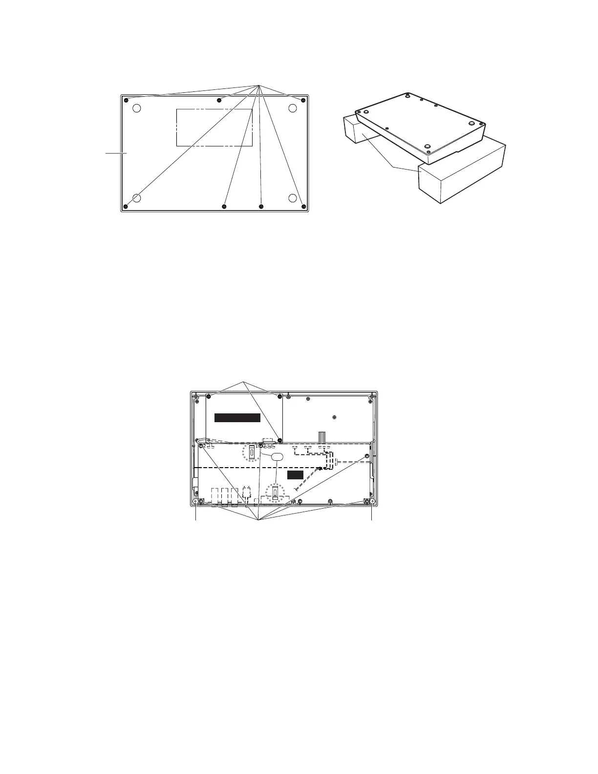
Bottom Assembly (time required: about 1 min)
1-1 Remove the seven (7) screws marked [180]. The
bottom assembly can then be removed. (Fig. 1)
* If you turn the mixer upside down for
disaasembling and assembling, put 2 wooden
bolsters underneath the unit at its both side ends to
protect PN sheet from being damaged. (Fig. 1-1)
[180]
Bottom Assembly
PLG150-DX
DM
[160]
[120][130] [140]
*1
*1
2. PLG150-DX Circuit Board
(time required: about 1 min)
2-1 Remove the bottom assembly. (See Procedure 1.)
2-1
Remove the tree (3) screws marked [160]. The PLG150-
DX circuit board can then be removed. (Fig. 2)
* Attachment consideration of the PLG150-DX
circuit board.
When installing the PLG150-DX circuit board, do
with connector assembly as shown in the fig 2-1.
Fit the PLG150-DX circuit board caring not to let
the connector assembly in it.
[180]: Bind Head Tapping Screw-B 3.0X6 MFZN2Y (EP600130)
[120]: Bind Head Tapping Screw-P 2.6X8 MFZN2Y (EP620100)
[130]: Angle, L (V655450)
[140]: Angle, R (V655460)
[160]: Bind Head Tapping Screw-B 3.0X86 MFZN2Y (EP620130)
(Fig. 1)
(Fig. 2)
(Fig. 1-1)
Wooden bolster
DX200
Bottom side