9
DX200
3.
DM Circuit Board (time required: about 2 min)
3-1 Remove the bottom assembly. (See Procedure 1.)
3-2 Remove the PLG150-DX circuit Board.
(See Procedure 2.)
3-3 Remove the six (6) screws marked [120]. The DM
circuit board can then be removed. (Fig. 2)
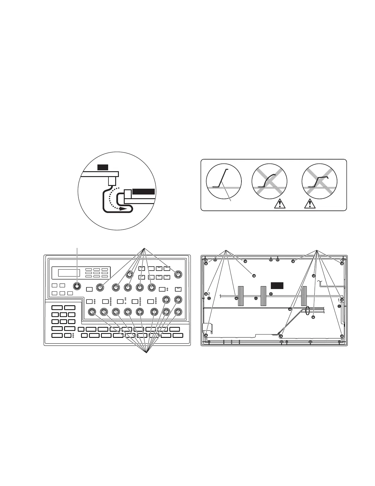
* Attachment consideration of the DM circuit board
Confirm that the DM contact terminal (110b),
which is on the backside of the DM circuit board,
is not distorted or bent. Contact it appropriately on
the bottom board assembly. Replace any terminal
when it is bent or broken. (Fig. 2-2)
DM
PLG150-DX
DM-PLG
Connector Assembly
CN5
CN1
orOK
NG
DM Terminal
SONG
PATTERN STORE
VELOCITYGATE TIMEPITCH
INST SEL BPM BEAT
[210] [200]
[200]
PN
[60][60]
4.
PN Circuit Board (time required: about 4 min)
4-1 Remove the bottom assembly. (See Procedure 1.)
4-2 Remove the PLG150-DX circuit Board.
(See Procedure 2.)
4-3 Remove the DM circuit Board. (See Procedure 3.)
4-4 Remove the seventeen (17) knobs marked [200]
and one (1) knob marked [210]. (Fig. 3)
4-5 Remove the fourteen (14) screws marked [60]. The
PN circuit board can then be removed. (Fig .4)
[200]: Knob K-CB (V4765800)
[210]: Knob (VU931600)
[60]: Bind Head Tapping Screw-P 2.6X8 MFZN2Y (EP620100)
(Fig. 3)
(Fig. 2-2)
(Fig. 2-1)
(Fig. 4)
DM Terminal (V7450500)