EasyManua.ls Logo

Yamaha PM-1000 User Manual

Yamaha PM-1000
27 pages
To Next Page IconTo Next Page
Page #1 background imageLoading...
Page #1 background image
FOUR
DOLLARS,

Other manuals for Yamaha PM-1000

Question and Answer IconNeed help?

Do you have a question about the Yamaha PM-1000 and is the answer not in the manual?

Yamaha PM-1000 Specifications

General IconGeneral
BrandYamaha
ModelPM-1000
CategoryMusic Mixer
LanguageEnglish

Summary

Identification of Parts and Controls

Main Components & Sub Assemblies

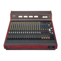
Overview of the console's main physical parts and functional modules.

The Input Module

Equalizer

Alters frequency response using Bass, Mid-Range, and Treble controls for tonal shaping.

Input Level Switch

Adjusts preamplifier gain for optimum input signal level and headroom.

Channel Fader

Controls the module's output level to the program mixing buses.

Master and Monitor Module

Master Fader

Sets the overall signal level for the main program outputs (Line A & B).

Headphone and Echo Module

Talkback and Oscillator Module

Meter Panel

Rear Panel

Line-A-Out and Line-B-Out Jacks

Redundant outputs for main program signal from Master Faders.

Monitor Out Jacks

Outputs for console audio from the Monitor Mix section.

Channel Input Jacks

Accepts audio from low impedance, balanced or floating sources.

Submixer Input Jacks

Accepts audio from auxiliary mixers or other sources to expand input capability.

Channel Inputs

Submixer Inputs

Playback Inputs

Talkback Input

Master In & Master Out

Installation

Power Mains

Instructions for connecting the console to AC power, including voltage requirements.

Theory of Grounding

Explains the importance and methods of proper grounding for audio systems.

Audio Connectors and Cable Types

Interface with Auxiliary Equipment

Cable and Connector Wiring Configurations

Wiring an RCA-Type Pin Plug

Step-by-step guide for preparing and wiring RCA-type pin plugs for audio cables.

Wiring a Male XLR Connector

Wiring a Female XLR Connector

Wiring a Standard Phone Plug (2-conductor)

Wiring a Tip, Ring & Sleeve Phone Plug (3-conductor)

Interconnections

Pads, Transformers and Direct Boxes

Attenuation Pad Resistor Values

Table providing resistor values for constructing T-pads and H-pads for signal attenuation.

Direct Boxes

Matching Transformer Box

Step-Up Transformer Box

Related product manuals